
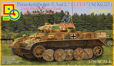
Panzerkampfwagen II Ausf L "Luchs" (Sd.Kfz123)
Light Reconnaissance Tank [9th Panzer Division]
Classy Hobby 1:16 Scale Kit No. MC16001
Review by Terry Ashley
Part 2 of 3
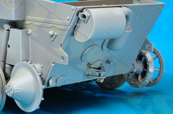
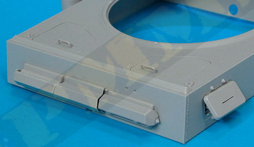
The largest item added here is the central exhaust pipe with cast armoured guard included, the bolt heads are nicely rendered but the armoured guard is smooth and lacks the slight surface texturing which is a feature of German exhaust guards of this type and roughing up the surface a little or using “Mr Surfacer” or similar will improve the appearance. This guard simply glues onto the hull and there are the usual mould lines that need to be cleaned from the exhaust before fitting.
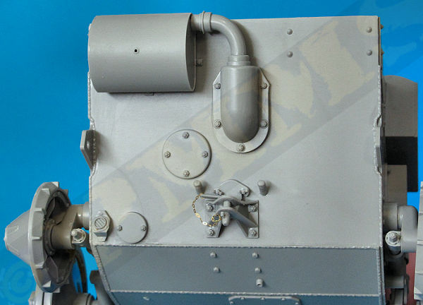
The large muffler is in three parts that go together easily with just the top and bottom muffler joins to be eliminated after the glue has dried and again adding texture to the muffler would add to the appearance. The muffler fits over the end of the exhaust pipe and sits on the two locating tabs on the rear hull without any problems.
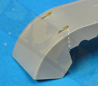
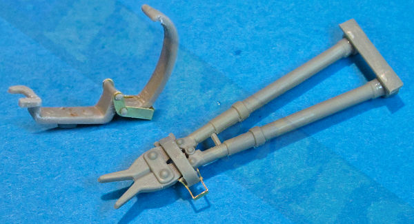
The rear tow coupling is an intricate moulding but there is a bit of flash to be cleaned and again the bolt heads are nicely done, the separate coupling pin (part A5) has fine etched chain to add but the instructions are a little confusing where the chain actually attaches and some additional reference would be helpful (see image)

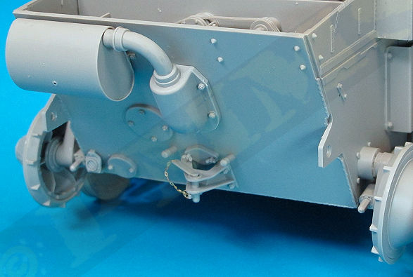
Just above the coupling is the moulded on starter crank port cap and this has two small butterfly bolt fasteners (parts D41) to be added and they need care removing from the sprue and in fitting, there is also the small reflector and a couple of other small fittings added. On the inside of the rear plate is the upper intake deflector (part A15) and two small fillets (parts H36, H37), these all fitting without any problems, just be careful to position the deflector correctly so it doesn’t foul on the fan bulkhead when fitting the rear hull, a quick test fit will ensure the proper fit.
The assembled rear panel fits snugly to the rear of the lower hull between the two tow attachment lugs with no trimming required. As mentioned the side welds may need some additional work to blend into join for a better appearance.
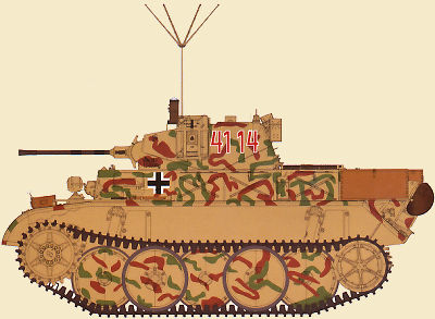
If you are building Option 1, tank 4134 there are two additional Jerry Can racks to be added to the rear plate, the racks are in plastic with etched top straps and there is a bit of fine flash clean-up needed for the racks before gluing the two halves of each rack together, you should assemble the racks, let the glue dry and clean-up the joins before added the Jerry Cans as this makes things easier.
The Jerry Cans are split in two halves with an etched middle bracket as well as having excellent engraved stencilling on the Jerry Can side with correct wording and symbols for standard Wehrmacht Jerry Cans, the top carry handle is a separate part that fits neatly into place along with a single piece closed filler cap. This cap is fairly basic for the scale but serves the purpose I guess.
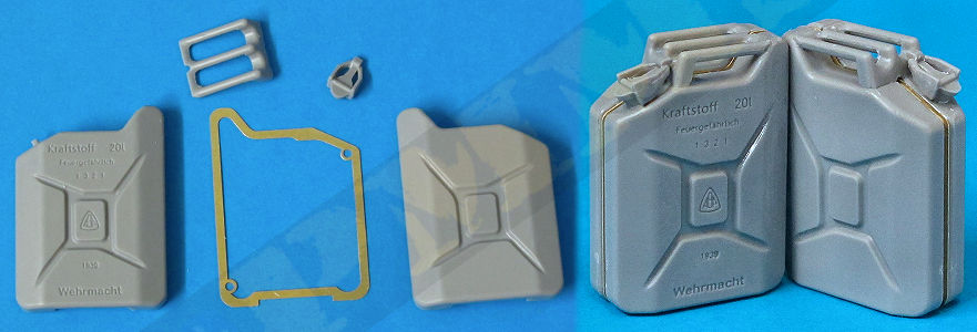
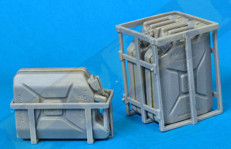
The assembled cans fit into the racks and secured in place with the top etched strap, the racks are then added to the rear hull plate although there are no locating holes so just position these by eye for the best alignment, as they were field mods a bit of leeway is possible in the positioning.
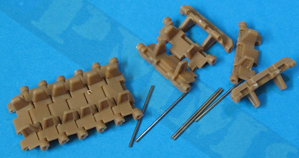
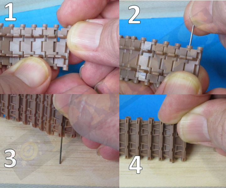
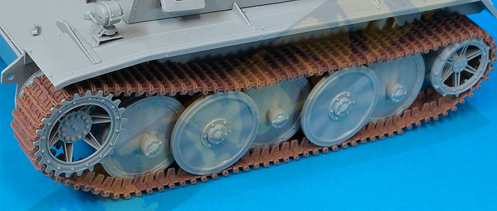
Assembling the tracks is very straightforward, after clean-up you just fit one link into the next (1) and then insert the steel pin just through into the first two track segments by hand (2), I then pressed the pin all the way through the links using a wooden block as a press (3, 4), if you have lined the two links up properly this pin should slip into place without any problems, the pins will hold in place without any glue but if one wants to slip out just add a small dab of cyanoacrylate to the end of the pin. Simply repeat the process to assembly the full track run of between 95 and 98 links depending on the position you set the idler wheel at earlier.
The assembled tracks fit very snugly around the drive sprocket teeth and allow the appropriate droop over the first pair of road wheels. Note as the links/pin fit is a little tight they didn’t articulate totally freely so just position the tracks for the best appearance.
The fenders are then attached to the hull with the fit very good and they butt up against the underside of the rear large hull side intake boxes to provide a very robust join. The large selection of tools and storage boxes can be added to the fenders depending on the option being modelled as indicated in the instructions.
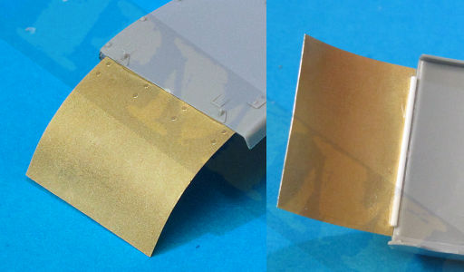
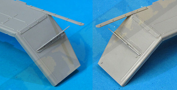
Fitting the original style front fender extensions (parts A9, A10) required some minor trimming of the inside edge of the fender to allow the fender to sit at the correct angle, see image. There are two small fender clips made from one plastic and one etched part to be added to the fender. If using the simple field mod fenders supplied in etched brass (parts P20) you need to cut off the two clip attachments on top of the fenders, then bend the brass fenders to the correct curve (I used the plastic fenders as a guide) and these are just butt joined to the ends of the fenders using cyanoacrylate. This doesn’t give a very strong join so I strengthen this by gluing a short length of thin plastic rod on the underside of the join to sit in the recess and give added strength to the join.
and the reinforcing rod added for the etched fender extensions.
View with the fenders added to the lower hull.
The tools are a bit of a mixed bag, some tools have the clips moulded on while others have them separate in a combination of plastic and etched clips. These clips combine thickish plastic with fine etched brackets and the plastic brackets need a bit of clean-up of both the mould lines and around the small pins that are designed to fit into the holes in the etched clips, some of these plastic pins need to be thinned to fit and care is needed not the damage the pins in the process. The thicker plastic and thinner etched clips not only look a little odd but assembling these so they are workable is rather frustrating to say the least.
We’ll look at the clip for the wire cutters here; firstly you have to thin down the plastic pins to less than half the original thickness without destroying them, then taking special care to get the proper orientation ease the pins from the first clip (part Cb15) into the lower holes in the etched clip (part P6). Then holding the etched clip firmly onto the plastic clip with tweezers so they don’t just pop out as you try to fit the second of the clips you virtually need to bend the ends of the brass clip outward to get the second plastic clip (part Cb22) pins aligned into the holes and then bend the brass clip back over the pins to secure them in place, sorry if that sound confusing but it took a few tries to master the assembly. After you do a couple of these you should get the hang of it, the pins on some of the other plastic clips are moulded thinner than on the cutter clips so should be easier and if this seems a lot of effort for a small tool clip it probably is and it maybe even easier to simply glue them in place around the tools as it will save some time.
Note the different thickness of the clips between the plastic and etched clips.
Maybe full etched brass clips would have been the better option, if so then ABER already produce a set of 1:16 etched German tool clips in set #16 013 that has clips of the style used with the ‘Luchs’ tools if you want to go that route?
A quick look at the individual tools, all need the prominent mould lines removed before assembly so I won’t mention this with each one:
The large Jack is a multi-part assembly that goes together well and has plastic mounting clips on the right rear of the hull but only for tank 4134, there is no indication where the jack goes for the other two options in the kit. Again the clips are a bit on the thick side and etched clips would have been preferred but that is not to be.
The wire cutters (part Cb21) is in one piece with separate end bracket that has two round cups that fit over the cutter handles; these have even more clean-up required as they are rather rough. There is a single tool clip with the plastic/etched clips as mentioned above.
The axe (part Cb7) has two of the plastic/etched tool clips with the bracket over the axe blade moulded in place and again this could have been in etched brass for a better appearance.
The shovel (part Cb6) also has the spade bracket moulded on as is the handle clip for a simple arrangement, the end of the shovel handle butts against the L shaped fitting moulded integral midway along the fender.
The fire extinguisher (Cb13) unlike the other tools has the securing straps and clips moulded with the extinguisher body and without wanting to labour the point separate etched clips would certainly improve the detail definition here. It has a separate base plate and two small etched fittings but you must watch when assembling this due to an odd thing with the instructions. There is only one extinguisher in the kit yet in Step 22 it shows it assembled as sub-assembly F and attached to the front left fender in Step 24, yet in Step 42 it again shows the extinguisher assembly with different etched fittings as sub-assembly Q and attached to the right rear fender in Step 45 for tank 4134 only. So you should be aware depending on the tank option being built to assemble the extinguisher as per Step 22 or Step 42 accordingly. There is no extinguisher decal label provided and it would have been nice for this to be included on the decal sheet to enhance the extinguisher finish.
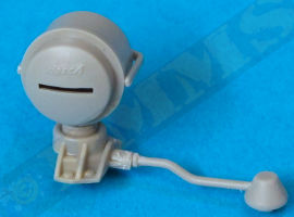
The crank handle (part Cb20) again is fairly basic with moulded on tool clips and Interestingly this crank does not get a mention in the Panzer Tracts plans, either on the overall plan view or the individual 1:10 plans for the tools, so not sure if this should be there as it’s hard to make out on available period photos?
The long wrecking bar (part Cb5) has the clips moulded on and this should also have an additional bracket for the angled head but this is not included.
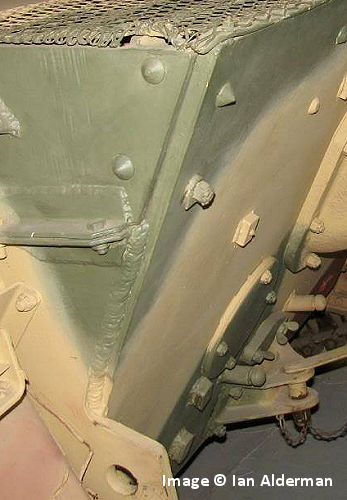
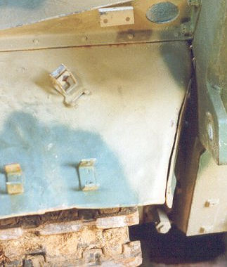
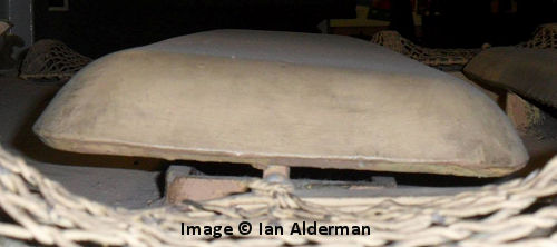
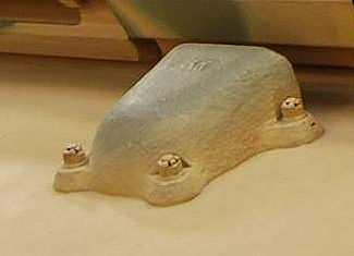
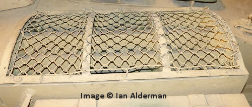
The two S-hooks (parts Ce1) have a single plastic/etched clip and a small U shaped bracket provided in plastic and is a little on the heavy side. The Panzer Tracts plans show the plastic/etched clip on the centre straight section of the S while the kit instructions have these around the end curve of the S and as I can’t find any period photos with the S-hooks in place it’s hard to say. This museum image with just the brackets seems to indicate the top clip is around the S curve but again this may vary like many other things between vehicles with the ‘Luchs’?
There are multi part storage boxes, storage racks and other equipment as indicated and again the location of these depends on the finishing option selected so check the instructions for what goes where but there shouldn’t be any problems assembling these items apart from the usual clean-up needed.
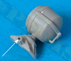
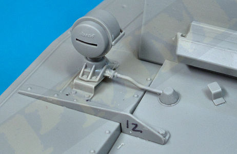
The convoy tail light is a three part assembly mounted on the rear of the left fender and the two headlights mounted at the front. These have the light body with clear plastic lens that includes the rib pattern on the ‘glass’ and screw heads around the rim of the body should you want to have the lights without the blackout cover, a nice inclusion, the separate blackout covers have the stylized “Bosch” logo embossed on the them plus three small bracket clips to secure the cover.
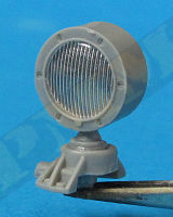
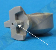
The separate base has nice details with just the mould lines to remove as well you need to trim the underside pin level with the bottom of the base so it can sit on the mounting brackets glued onto the fenders (parts Cb8, Cb9), also to attach the electrical conduit (parts D31) you should drill a small hole in the base connector for a better fit, this conduit is not glued until you fit the glacis later.
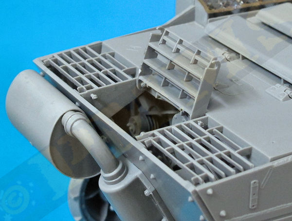
The central grill section is separate and this can swing open after assembly like the real thing and as with the side grills there is a bit of clean-up needed before fitting the larger and smaller grills together. After clean-up take care to test fit the smaller grills making any adjustment needed to get a snug fit between the larger grills and then carefully add the smaller grills in place, there are a couple of etched clips to be added also with the fully assembled grill work (not shown in the assembly images).
View of assembled grills with centre section in the open position.
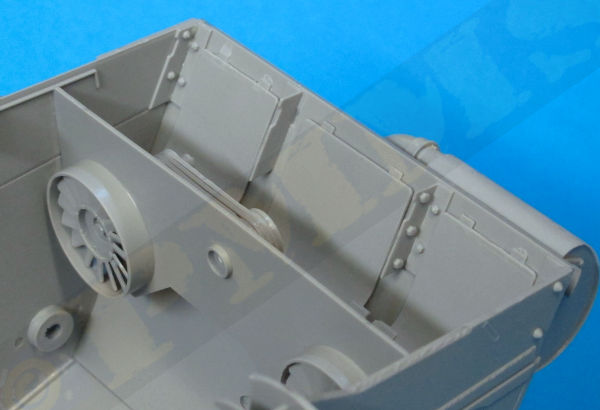
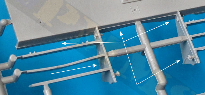
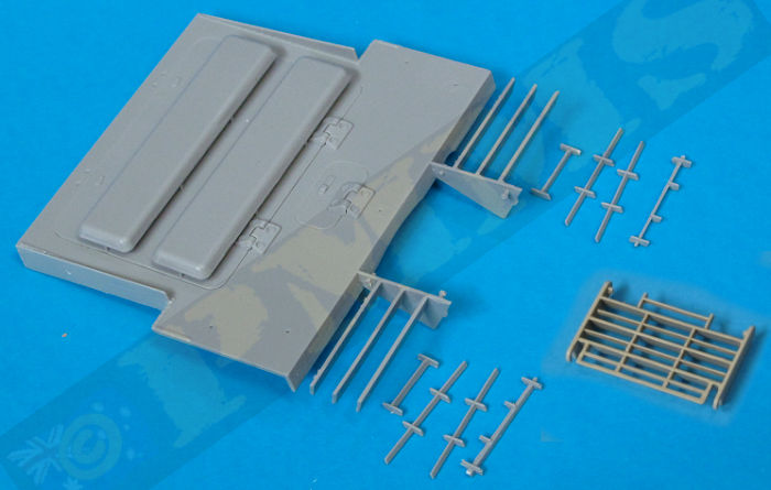
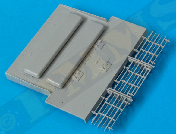
The separate engine access hatch (part A28) has separate armoured cooling intake covers and these will need casting texture added as well as the underside edges have a distinct undercut bevel not present on the kit parts and this can be added by shaving slightly with a #11 blade or careful filing, the covers can then be glued in place on the six support post per intake cover, the fit of the large and small access doors to the deck is very good giving a very snug and tight fit without any trimming needed.
There is also smaller access door (part H7) and five two-part tow cable brackets added to the rear deck, these need careful handling while removing the mould lines, also take care to note the part numbers as these are differently numbered parts for the different positions of the brackets on the deck. The steel cable supplied can be added to the deck if you wish fitted to the cable end eyes (parts D46) and the assembled deck is put aside for fitting after the upper hull casemate sub-assembly is done.
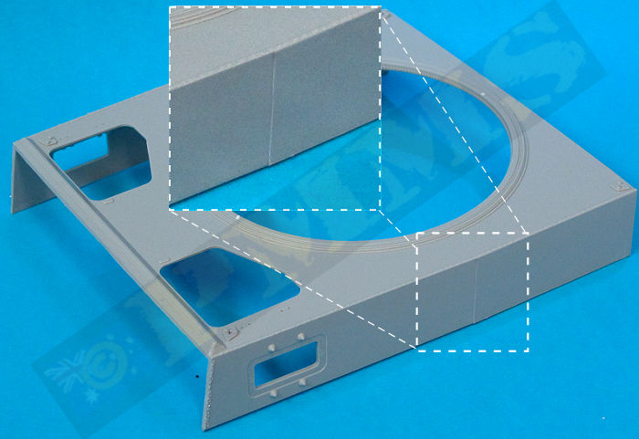
On each side of the casemate are large mould lines where the rear side is actually slightly higher than the side in front of the mould line, this requires a bit of work to get the side panel smooth. I used a #11 blade to shave away the raised side of the line and then finished with the fine wet-n-dry sanding to get a perfectly smooth finish. Also note there is a slight change in angle of the side plate at this point but no join line so smooth out the seam accordingly but leave the angle corresponding to the top hull profile.
The two crew hatches actually hinge down into the interior and as there is no interior detail it’s best to glue these in the closed position, an odd thing is on the inside you get separate securing latches (parts H16, H17) that can be fitted in the open or closed position but on the outside these latches are moulded with the top plate in the open position so you really need to shave these off and remake from thin plastic card to show in the closed position.
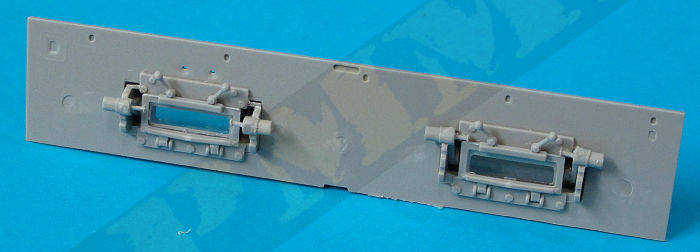
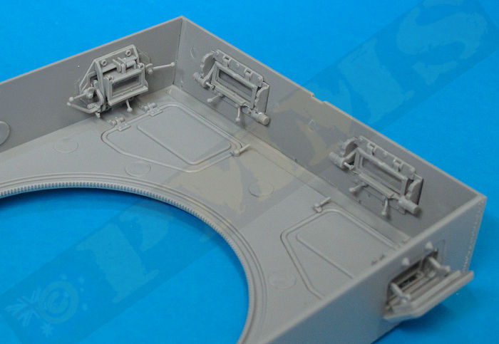
The two front side vision ports have very detailed inside visor mountings with clear vision “glass” plus levers, it’s a shame these are totally hidden after assembly and you can bypass these to save a bit on assembly time if you wish. The outside visors have nice contours and vision slit and can be fitted in the open or closed position as you wish.
The front Driver’s plate also has the full visor detail on the inside and again unless you have the top hatches open these are totally hidden after assembly so you can again omit these to save a bit on assembly. This is a bit of a blessing as the fit of the visor frames into the recess in the front plate required a fair bit of trimming from the front of the visor mounting before they would fit properly so bypassing these will save a bit of hassle here.
The outside of the Driver’s plate has the inner visor armoured covers with separate armoured visor flap than can fitted in the open or closed position as required, there is also the false visor fitted between the two actual visors as per the real thing and the fit of the driver’s plate to the casemate is very good without any trimming needed.
With the Driver’s plate glued in place you will need to add the weld along the upper join line; this weld will fill in the panel join line nicely to improve the appearance here.
The rear plate is an excellent representation of the real thing properly indented at the bottom with the vent and other details and glues easily into place, just make sure the two lower tabs sit level with the end of the casemate side wall. This plate is totally hidden when the rear engine deck is fitted so don’t worry much about the details.
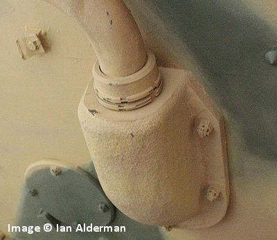
The large antenna pot on the right side is moulded as a single part and due to the moulding process there is a large mould line around the middle of the pot, the top is also angled in slightly, a moulding requirement to allow the part to exit the moulds. To remove the mould line I again used a #11 blade to shave this down and also the side of the pot to get these as vertical as possible, the end result still had a slight angle inwards at the top but a lot less noticeable than on the original part.
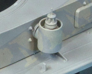
The pot can be fitted at any angle by way of a notch on the locating neck and ratchet teeth inside the hull locating hole with the pot held in place by a retaining plug (part G2), this allows you to position the pot fully raised or lowered in the stowed position or anywhere in between as you wish.
Included with the kit is the star aerial with the main mast (part A20), insulated base (part H23) and the six thin star aerials (parts Bd29), these are moulded quite thin and care will be needed removing from the sprues and cleaning up the attachment burs, the fine mould lines are best removed while the parts are still on the sprues to give some support. The assembled star aerial is added to the armoured pot but for obvious reasons it’s best to leave this aerial off until last.
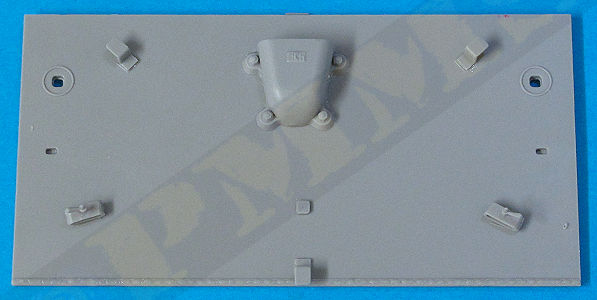
Image of vent cover showing the cast surface texturing.
Also note that not all the vehicles had the tow cable attachments on the glacis, period photos of 4114 clearly show they are not there but photos of vehicle 4134 show the brackets fitted on the glacis. Available photos of 4121 do not clearly show the glacis so can’t say for this vehicle option.
One point of note is the much photographed Bovington ‘Luchs’ doesn’t have the additional smaller ribs (parts Bd2) inside the intake boxes nor do some wartime period photos while other period photos clearly show the additional ribs so these seem to be a bit like the elusive rear intake mesh, some do and some don’t but working out which is which is the question?
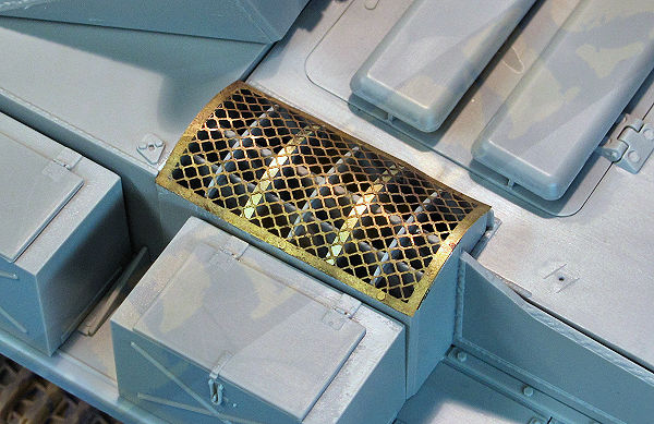
Image of Bovington 'Luchs' intake grills
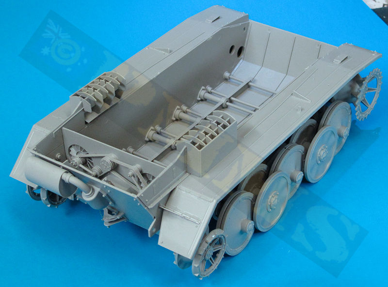
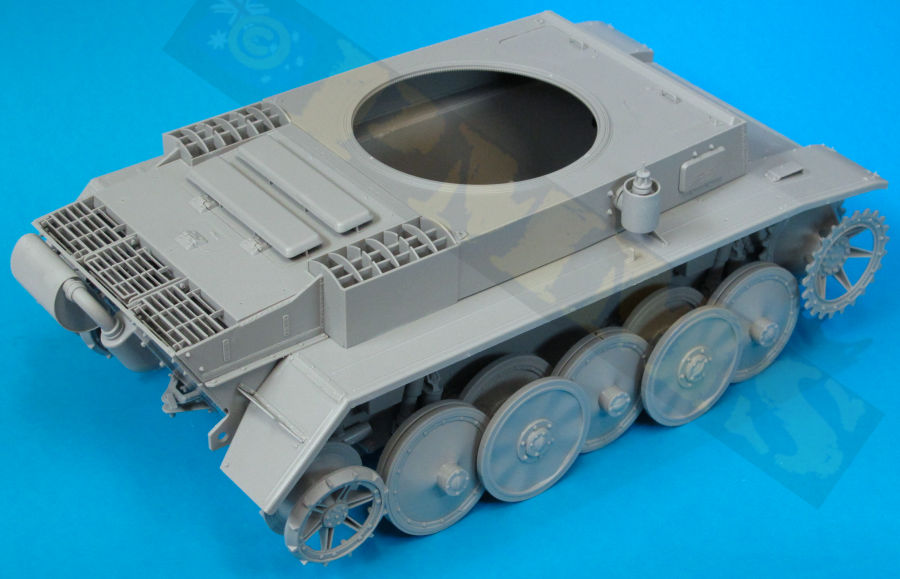
With the screens in place the sub-assemblies can be added to the lower hull starting with the front glacis, then the central casemate and finally the rear engine deck. The fit of these parts to the lower hull/fenders was excellent with no trimming needed at all, if fact in the build photos of the assembled hull the casemate and engine deck are not glued to the hull, just sitting there such is the good fit while the glacis is just lightly spot glued.
to Review Part 3 - Conclusion and Sprue images
back to Review Part 1 - Introduction
Please to help the reviews continue, thank you
