
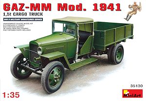
GAZ-MM Cargo Truck 1.5t Mod.1941
Miniart 1:35 Scale Kit #35130
Review by Terry Ashley
The kit consists of:
321 parts in light grey plastic
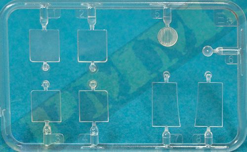
7 clear plastic parts
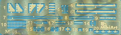
42 etched brass parts
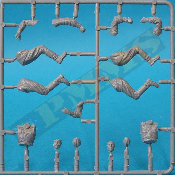
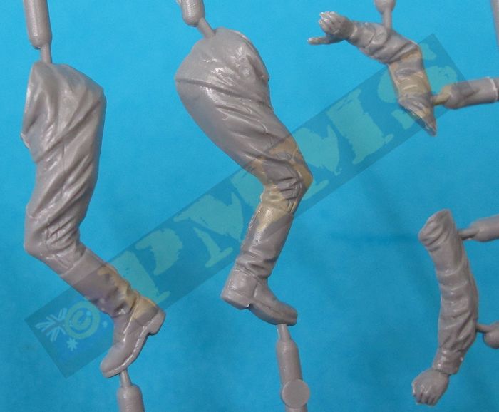
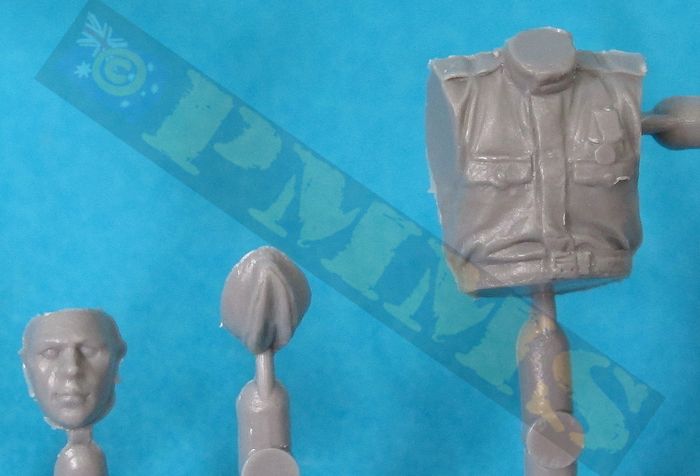
15 additional figure parts
16 page instruction booklet
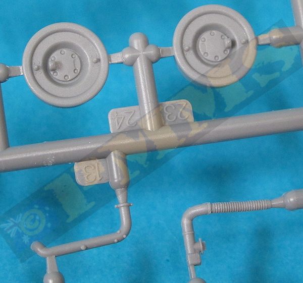
The quality of mouldings is very good overall with few if any visible pin marks and just a minimum of flash with the main clean-up being with the usual mould seam lines and those on the small and thin parts need care while removing, also the sprue attachments on some parts needs care removing to avoid damage to the parts. A few of the small parts were actually broken on the sprues and needed repairing before use. Oddly the same parts were broken in the same places in all three kits I have which would indicate some stress on the parts, but they were easily glued back together so it was only a minor hiccup.
Dimensionally the kit measures out well against available plans and data in the Tangograd and Tank Power books listed below with the details matching period photos and data very well indeed although the number of parts doesn’t make for straightforward assembly in some areas, most notably with the suspension where there are some very delicate parts. With the build below I have only assembled the main structures to test the fit etc. with all the smaller items such as headlights, bumpers, door handles, wipers and the hood and rear tray latches plus the etched parts still to be added, I also assembled some sub-assemblies differently than indicated in the instructions as I found a couple of areas where there is potential for problems if not careful. It is of course up to the individual if they want to follow this or build as per instructions, the variations are just suggestions.
The two chassis frames join together with several cross members and you must ensure the front cross member (part A83) is set perfectly at right angles to the chassis frames as this has a direct bearing on the location of the radiator which in turn the fit of the engine hoods, more on this below. You also need to ensure the chassis assembly is perfectly square and level before the glue dries as everything else in the kit fits to the chassis and this must be done correctly to avoid follow on issues.
The rear cross member has the rear tow pintle and inner bracket with two angled support beams added while at the front is the bumper beam with crank handle bracket. Added under the rear chassis is the spare tyre and support bracket this has very delicate side attachment brackets that do need care during and after assembly as these two side brackets (parts Fa12) are the only thing holding the spare tyre to the chassis.
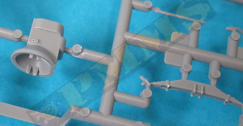
With the rear suspension you should firstly glue (and let dry) the large leaf spring units and supports to the chassis, the rear differential and drive shaft unit is quite straightforward and this is attached to the leaf springs. There are additional thin support rods and linkages added to the suspension and the completed assembly is quite delicate and you shouldn’t exert any undue pressure on the axle/leaf spring joins.
The front suspension is quite straightforward but there are some small parts that need care during assembly, the attachment points for the diagonal leaf springs are very delicate and will break if too much pressure is put on the suspension after assembly so take care. There are additional steering rods added between the suspension and chassis but the wheels are not designed to be steerable, you can position them at an angle to animate the front wheels but they are fixed in whatever position you choose. The assembled front suspension is then attached to the chassis cross member (part A83) and this should be left to dry completely before fitting the wheels to ensure it stays where it should.
The radiator is made up of two main parts with a separate top filler cap as well as a small etched name badge on the front. The detail on the radiator mesh is quite subtle and assembly straightforward but you shouldn’t glue the radiator to the chassis cross member (part A83) at this stage. This is because as mentioned above the position of the radiator dictates the proper fit of the four separate engine hood sections so you should leave the radiator off until after fitting the cab and then use the hood parts as guides to get the radiator in the perfect position as any small miss-alignment of the radiator will see the hood doors not fit correctly.
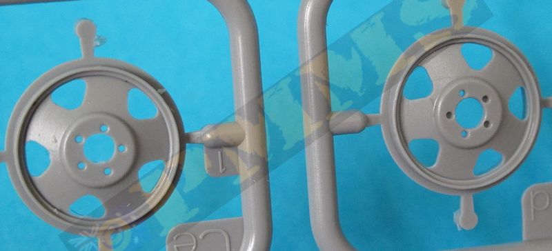
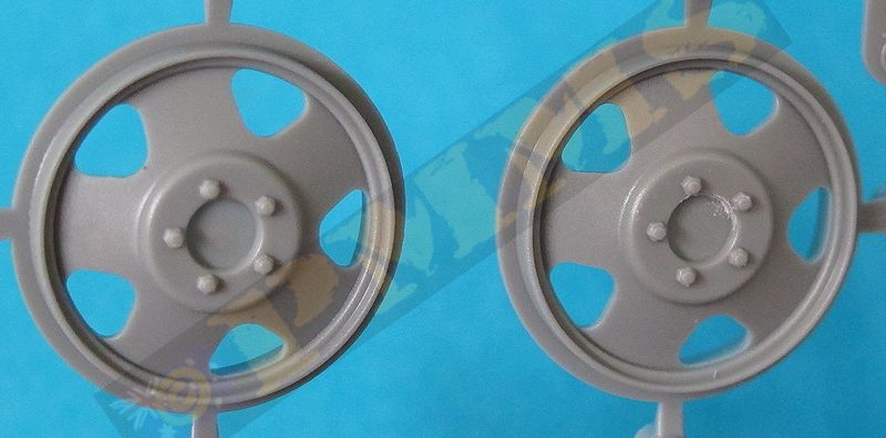
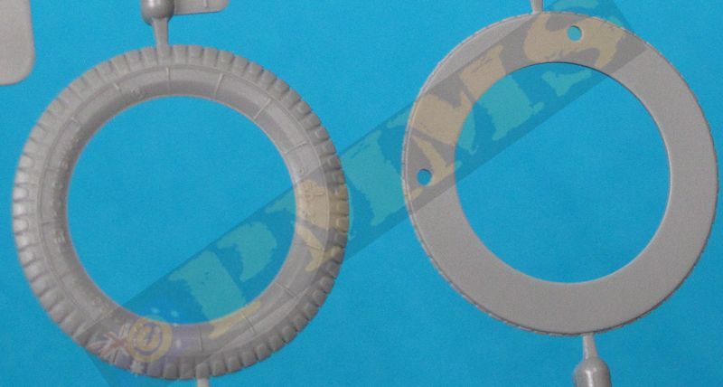
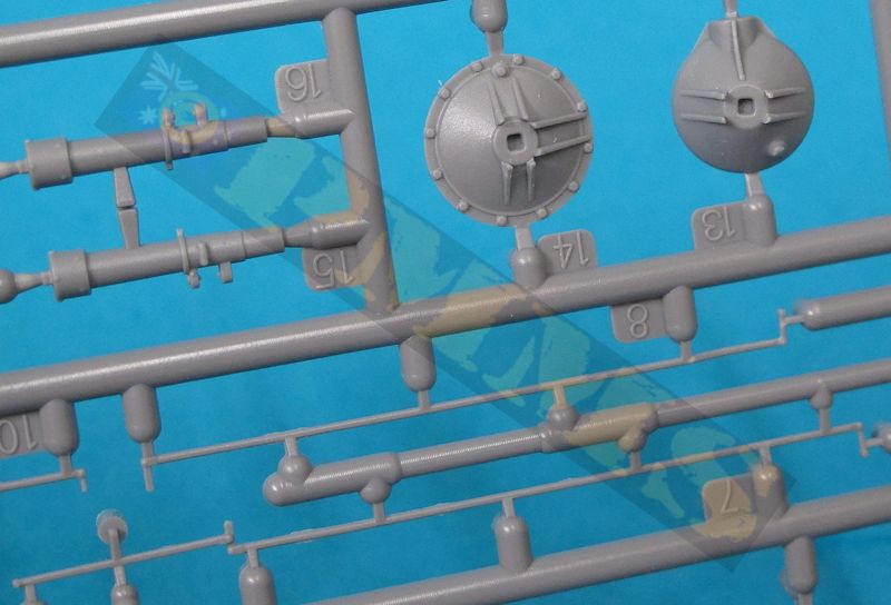
Assembly is straightforward really with parts C1 to C3 joined in one sub-assembly and C4 to C7 in another sub-assembly, the first sub-assembly (C1 to C3) is then added to the front of the wheel rim and sub-assembly (C4 to C7) to the rear of the rim, note the locating holes will only fit one way, so don’t force it, if the fit is not precise just turn the tyre section around till it does.
Take note of the different rims for the front and rear wheels during assembly, once the wheels are assembled the two rear wheel rims can be joined to form the duel wheel arrangement. The tread pattern has excellent definition but a light sanding with wet-dry will ensure the tread is nice and even without any lumps or bumps. The rear brake drums and wheels can be added to the axles and then all four wheels should sit evenly on the floor provided you ensured everything was square during assembly.
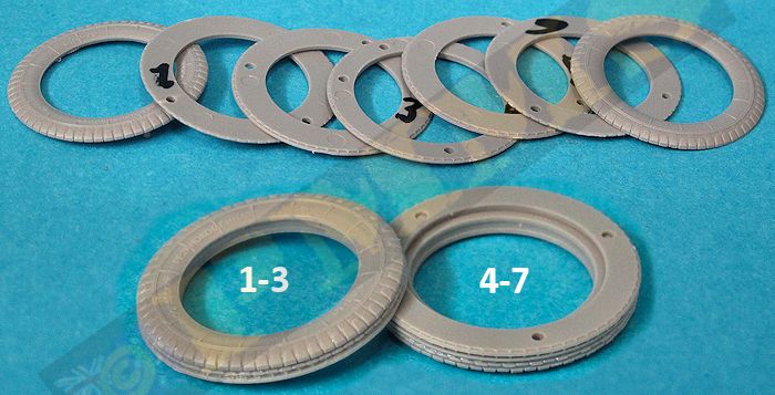
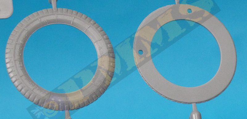
1-3 assembly added to outside of wheel rim disc then 4-7 assembly added to rear of wheel disc.
Note the small lugs and holes only align one way so don't force the sections together, just turn the tyre section around
till it fits neatly into place, this will ensure the proper tread pattern alignment.
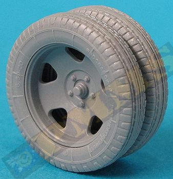
Image of assembled front wheel.
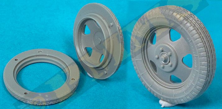
Image of assembled rear wheel assembly.
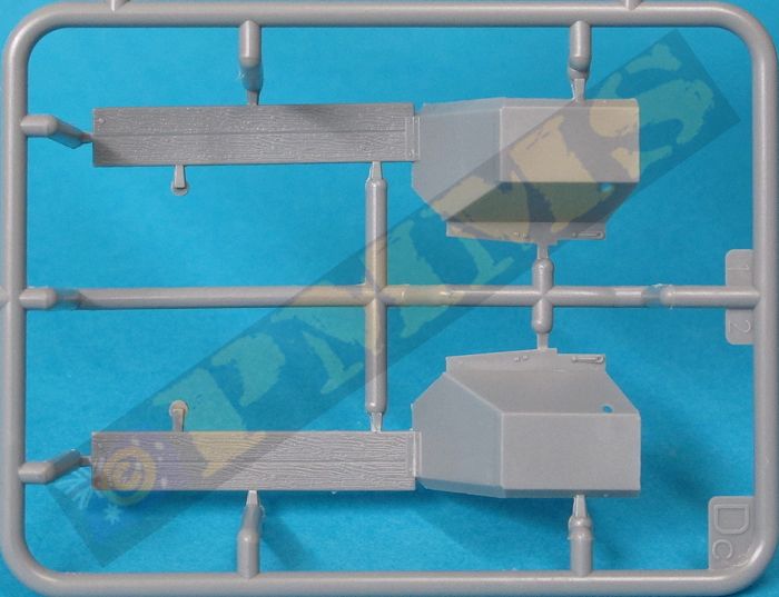
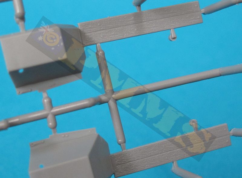
The two large front fenders can be added and the wooden side steps have very subtle wood grain texture included along with the underside indentations that match to the chassis ensuring they are positioned correctly but due care is needed for the best fit. There are numerous other smaller parts added to the chassis such as the fender supports, rear tail light assembly with etched parts for added detail as well as the front bumpers and rear tow hitch.
Overall the chassis and suspension parts fit well but there is potential for problems if not careful with the rear suspension alignment and the position of the radiator as indicated above.
Extreme care is needed when gluing the upper cowling (part A97) to the inner instrument panel (part A38) and in turn the windscreen frame (part A101) plus the two side body panels (parts A39, A40) as there is potential for miss-alignment and unsightly gaps at the sides if not careful assembling these parts. It also helps to add the firewall (part A66) at the same time to ensure the side body panels are correctly positioned, but with due care the fit is good.
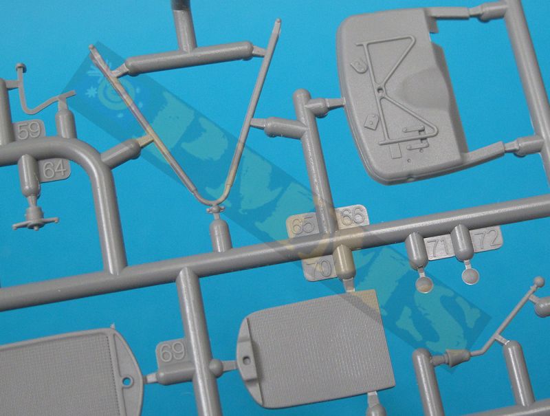
Once this assembly has dried the clear windscreen with additional etched parts for the side brackets and windscreen wiper can be added, note the windscreen can be fitted closed or open and the side etched brackets fitted accordingly. There are also additional detail items added to the firewall as well as the inside driver’s foot pedals and gear levers as well as the seat cushions on the floor frame and rear wall. The separate instrument cluster has a very small plastic switch added and the two part steering column and steering wheel can also be added.
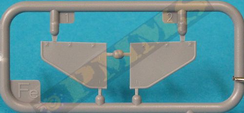
When fitting the rear wall and roof it’s advisable to fit the two small side panels at the same time to ensure the correct angles of the parts, there are numerous very small etched tie downs added to the panels and rear cab wall to add some good definition to the assembly.
When adding the rolled up canvas door covers it's best to cut away the moulded on door hinges as these just get in the way and will make for an easier fit of the door rolls.
Obviously the cab interior would need to be painted along the way and the completed sub-assembly can then be added to the chassis with two small lugs under the cab matching to those on the fenders for the proper alignment which shouldn’t pose any problems.
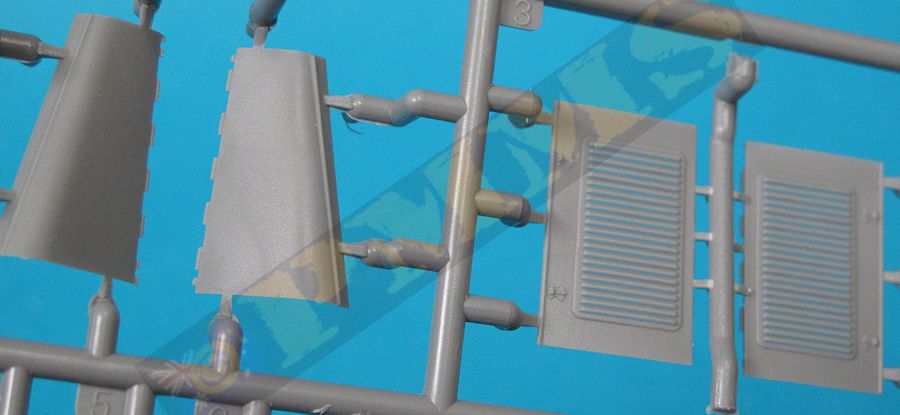
Once the cab has been attached to the chassis you can then proceed to glue the radiator in place on the chassis cross beam using the two hood side panels as ‘spacers’ to ensure the proper alignment with the radiator in place. The hood side panels have the louver slits moulded with fine gaps but you may want to open these a little more with a fine #11 blade to improve a little, the two top hood parts have inner hinges that fit together precisely along the centreline but the inner hinges on the lower edges and those on the side panels are best cut off as these just seem to hinder the panels mating together properly.
You can position the hood doors closed or folded open to show off the engine should you wish and there are more very small grab handle and latch parts added to the lower hood doors for excellent detail.
There are also the very finely moulded head light mounting and two part head lights with clear plastic ‘glass’ as well as the thin bar added between the fenders with the two part horn added and this delicate detail gives and very good air of finesse to the model but of course needs careful handing as they are also quite fragile.
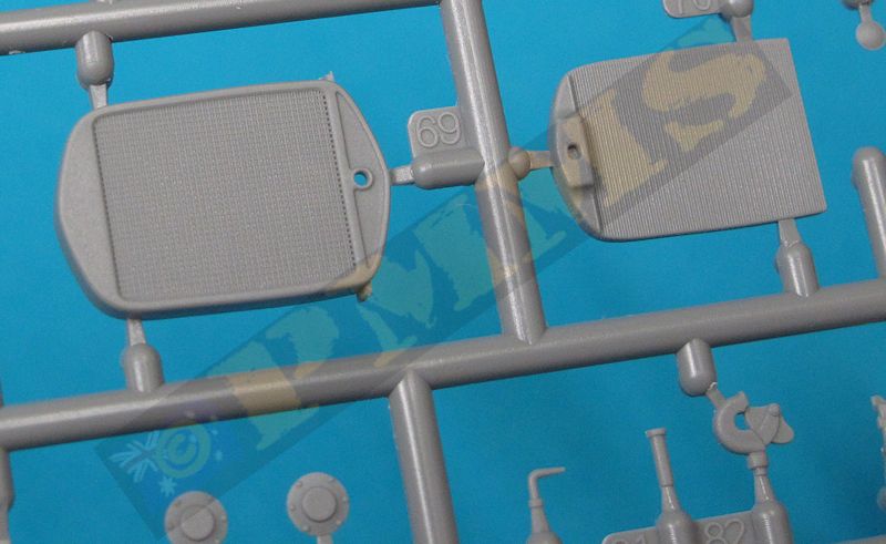
On the underside of the floor are four small plastic hooks and the cross support beams that fit perfectly without problems as do the upper sides. The side panels have additional small plastic brackets added and the rear gate can be fitted raised or lowered as required for a fairly simple and straightforward sub-assembly that then fits neatly to the chassis without problems.
The three options are:
- Transport column, battle of Stalingrad, the Don front, January 1943.
- Unknown unit, the battle of Kursk, June 1943.
- The Leningrad front, region of Vyborg, summer of 1944.
A couple of the areas need care as there is scope of miss-aligned parts if not careful such as the cab sides/top cowling and the fairly complicated rear suspension but due care should avoid any major problems.
The kit builds into a superb model of the 1937 GAZ-AAA truck but is not for the inexperienced modeller due to some fairly complex assembly sequences and the fine parts included and is applicable to many situations and scenarios as it was in service for much of WWII.
Rating 9/10
Click on thumbnails for larger view


Build Images
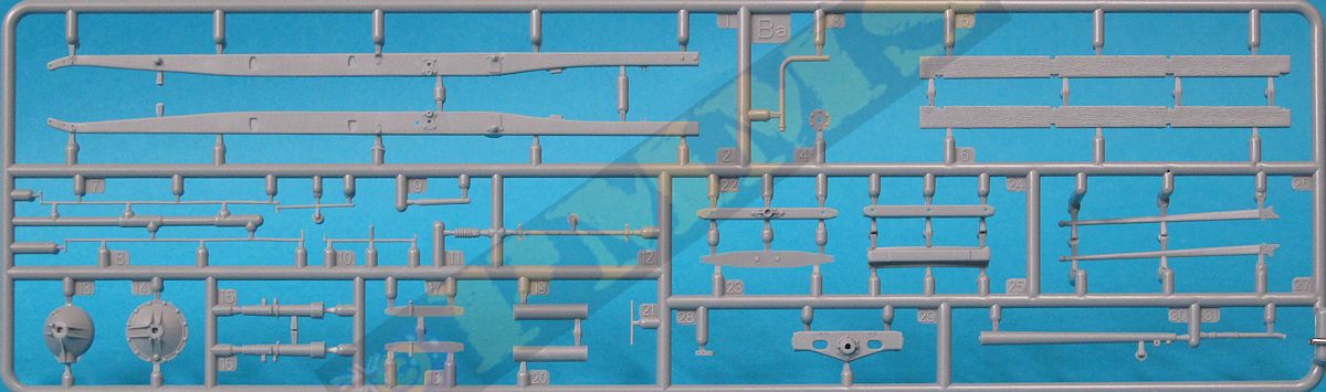
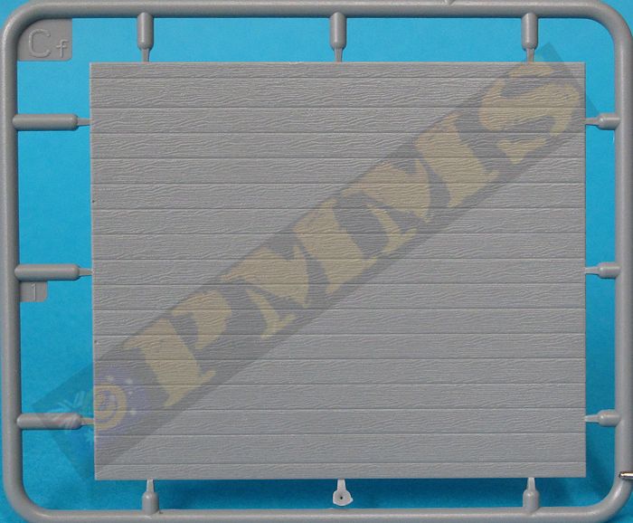
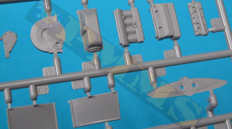
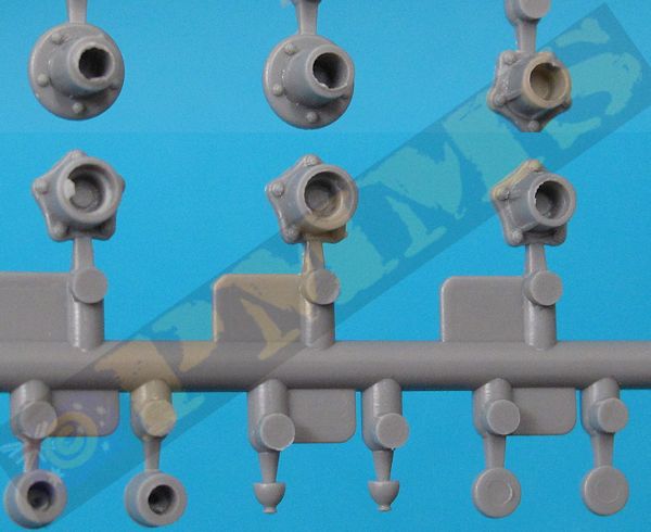
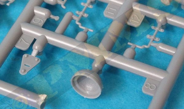
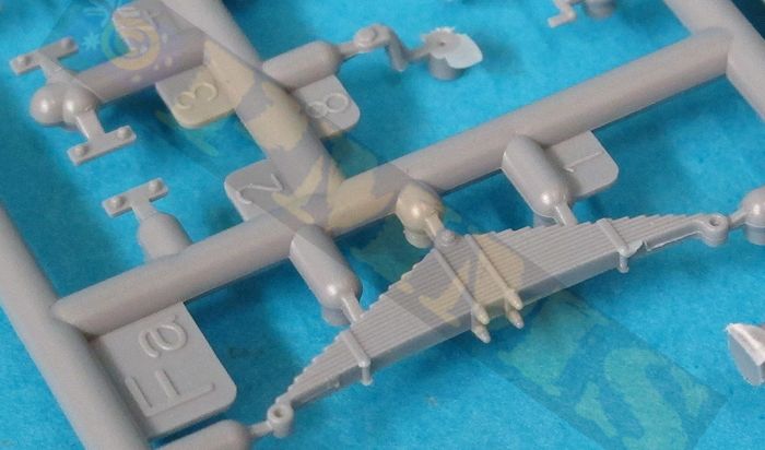
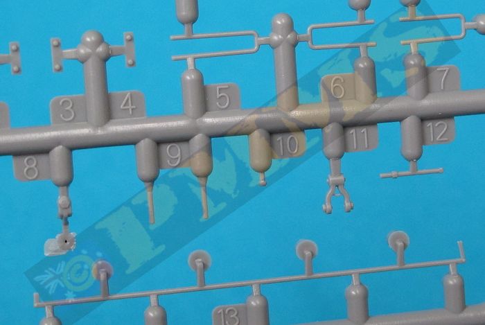
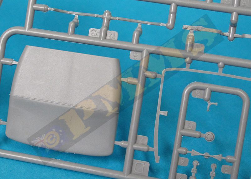
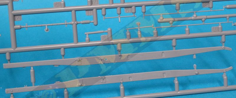
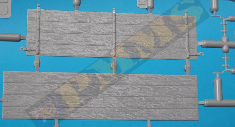
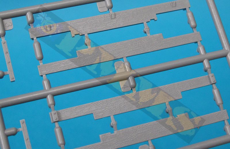
Sprue detail images


| Soviet Trucks of World War 2 Tankograd Soviet Special No.2007  |
Sowieckie samochody pancerne Vol.II Tank Power Vol.XXXII Wydawnictwo Militaria No.256  |
 and
and 