

T41 Workable Track Link Set
Miniart 1:35 Scale Kit #35322
Review and assembly guide by Terry Ashley
This set of T41 workable tracks is also included in all of the Miniart M3 Lee kits release to date.
A bit of technical stuff, the actual T41 track dimensions were:
16" wide
6" pitch (pad width)
3 ¼" thick
This equates in 1:35 scale to:
11.62mm wide
4.35mm pitch
2.36mm thick
The kit tracks were measured using electronic callipers and averaging out over 4-5 measurements taken as there were minor differences noted on each take.
11.62mm wide
4.25mm pitch (-0.1mm)
2.45mm thick (+0.09mm)
So, as you can see all measurement are either exact or less than 0.1mm difference which is really getting into the extreme nit-picking category and certainly nothing to get excited about and for all intents and purposes good to go.
- M3 Lee
- M3A1 Lee
- M3A2 Lee
- M3A3 Lee Early
- M3A4 Lee Early
- M3A5 Lee Early
- M4 Sherman Early
- M4A1 Sherman Early
- M7 Priest Howitzer Early
- M31 Armored Recovery Vehicle
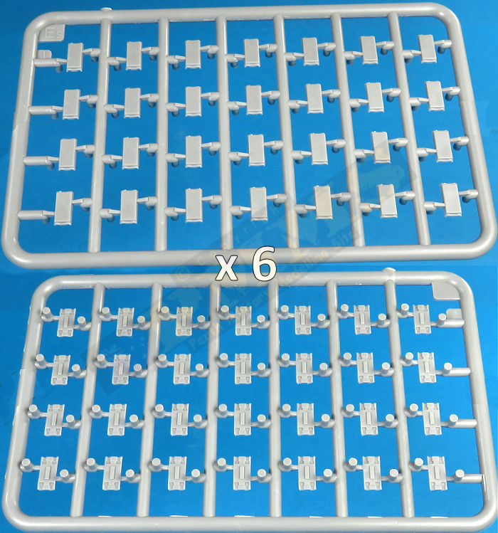
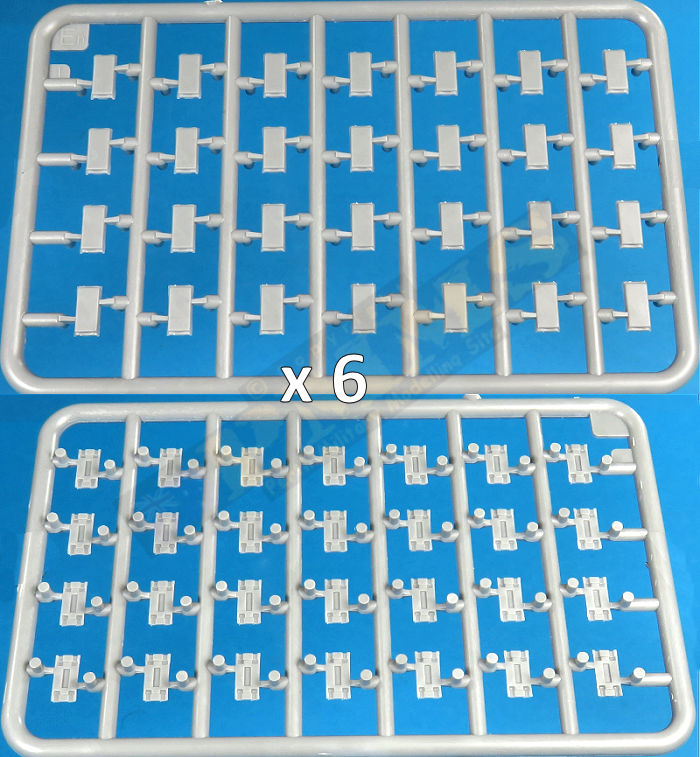
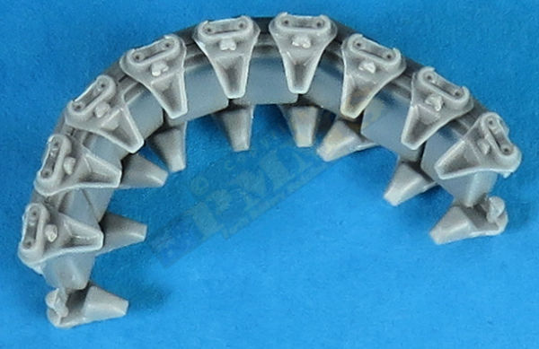
Track parts removed from sprues and sprue burs trimmed ready for assembly
The quality of the mouldings is excellent with crisp clean details overall, although there is some fine flash on some of the end connectors, this is on about 6-7 end connectors at the same position on every sprue runner with the amount of flash varying on each, the remaining end connectors were free of any flash. It is best to remove this flash while the end connectors are still attached to the sprue runner for ease of handling.
Also note the half circle notch on the ends of the short track pins.
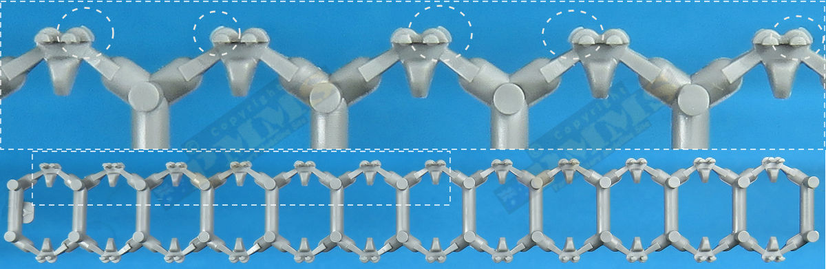
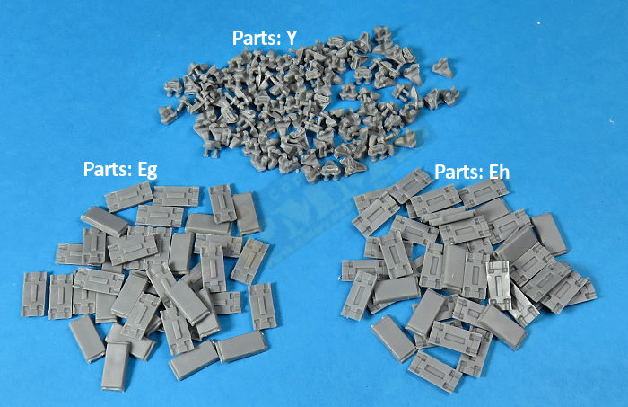
Each track pad is in two halves and being a flat rubber pad both sides there's not a lot you can do to mess these up, the two end connectors were shared with the adjacent link with 79 links making up one full track run. The end connectors are very well done with good detail definition including the retaining bolt head.
The links are designed in a way that allows you to assemble these as workable or just glued together fixed in position and as this is live track with no sag there is no need to assemble the lot as workable unless you really want to? Each end connector has two short pins with half round notches on the ends that fit into indents in the track pads.
You must of course as with any plastic type tracks remove the parts from the sprue runners and clean-up the attachment burs, this is quite a straightforward operation with the plastic being quite easy to work with but it does take a little time. For the end connectors, I cut these using a sharp blade as close to the part as possible and then held these firmly in a pair of stout tweezers while trimming any remaining burs. Once you get into a rhythm as with any individual track the clean-up is soon done ready to assemble.
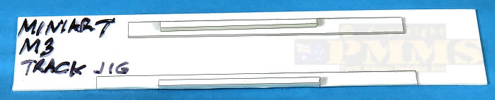
No assembly jigs are provided and it can get a little tricky when fitting the end connectors into the track pads to make workable links and for this I made two assembly jigs from plastic card and strip to make things easier, one for the start-up link and the other for the remaining longer track runs.
The trickiest assembly is the starting links for the workable section as this required four loose end connectors to be captured between one track pad halves, not an easy task when everything is loose and you need to be very careful where you put the glue so the result is actually workable track.
To this end I made a small jig that holds three track pads and the four end connectors with the jig making sure these stay where they should be while gluing the inner pad half to trap the four end connectors in place. The use of the three links was to, 1. Assist in aligning the four loose end connectors and 2. Making sure the middle link doesn't go anywhere during the process.
The image below shows this jig and as it's white plastic card that basically gets washed out by the lighting, I have also drawn the outlines of the jig to show how it was made, the dimensions obviously match those of the kit track pads and end connectors.

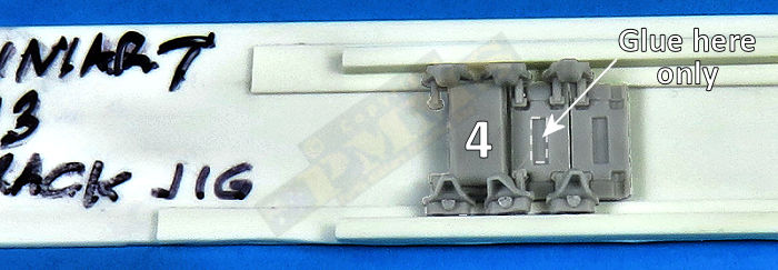
Assembly sequences for the 'starter' workable link.
1. Place the three outer track pads in the jig.
2. Place the four loose end connectors in the jig resting on the pads and add glue into the central trough on the pad,
the glue should be about level with the top of the trough but not overflowing.
3. Fit the inner track pad trapping the four end connectors taking care not to get any glue on the pins as per the text above.
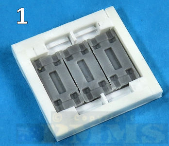
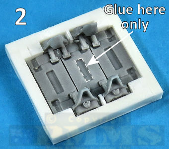
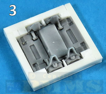
The images above show the starter assembly sequence and once this is done the remaining workable links are easier to fit as only two end connectors are loose for each subsequent join and for this a simple longer jig was used consisting of a base sheet of card, two card pieces the height of the half track pad added to form a channel for the outer half of the track pad (part Eh1) and then two strips of outer plastic beams to hold the end connectors upright when fitted to the pad.
As you glue the inner pad half to trap the end connectors it's essential not to get any glue on the end connector pins to retain workability and after gluing each one, I pressed the pad halves together firmly with the tweezer points for 30 seconds to let the glue 'grab' and then tested that the pins in fact remained movable. Any that had contact with glue I moved back and forth until the glue grip was broken and they moved freely, then proceeded to the next one, this is safer than assembling the full 14 links only to find a link or two had glued solid at the end.
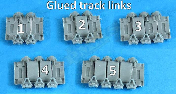
With the two 14 links workable sections done you can move on to the lengths glued completely together.
4. Add the 'starter' link to the jig plus two more link halves and two end connector, add the glue as before just in the pad trough.
5. Glue the inner link trapping the end connectors again checking to make sure no glue has got onto the pins.
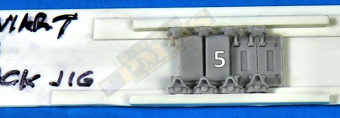
6. Continue until the required number of workable links have been assembled.
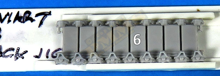
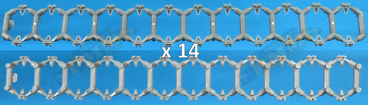
The partly assembled length of 14 links for around the drive sprockets and Idlers.
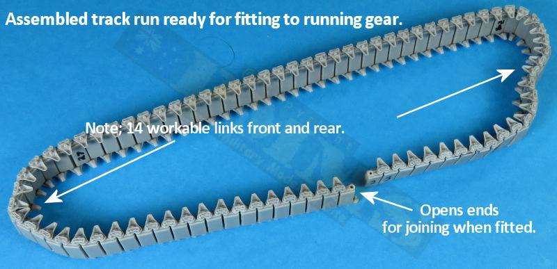
Assembly follows the same steps as with the workable tracks apart from gluing the pins and pads together so it's a lot quicker and I assembled the full top run of 30 links as one length but glued the bottom run into two sections with 11 and 10 links respectively to allow the ends to be joined as you fit the tracks around the running gear. The ends of the workable and solid track sections were joined using the same method as before forming the complete track run with the ends unjoined.
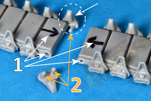
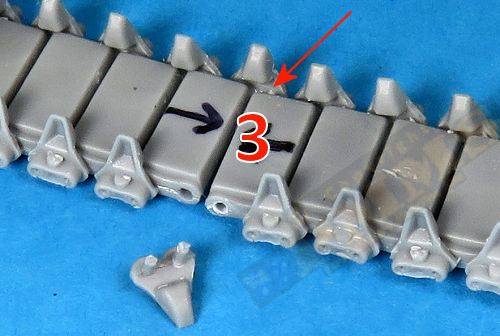
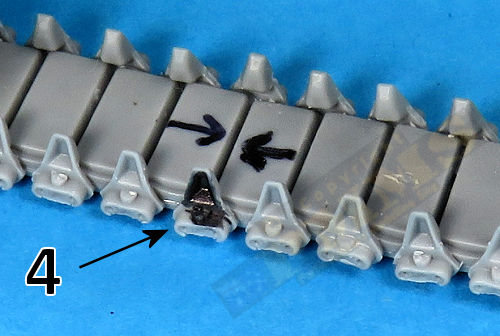
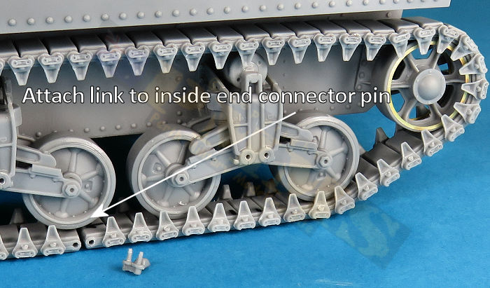
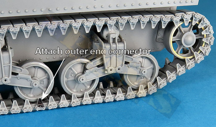
The exposed pin on the inner end connector and two pins on the loose outer end connector had the small notch trimmed off leaving a straight pin (Step 2 below). To join the ends after fitting the track around the running gear you simply fit the inside pad hole over the exposed pin (Step 3 below) and then fit the loose outer end connector pins to join the track runs together (Step 4 below), I found that the track tension held the end connectors in place without the need for glue allowing the tracks to be disconnected at any time by reversing the process, i.e. taking out the loose end connector and disconnecting the inner connector pin, all very simply. See images.
Images showing the above sequences with the track fitted to the running gear.
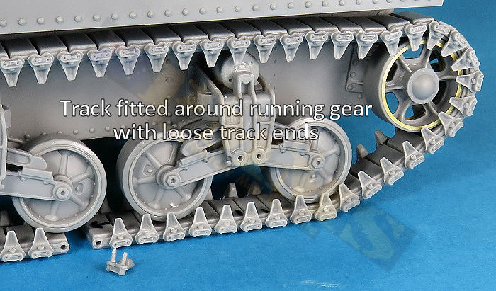
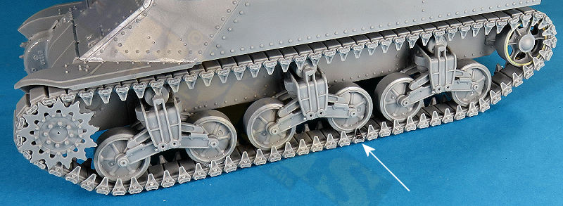
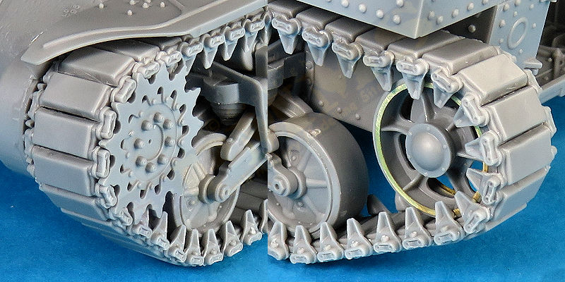
Overall views of the fitted track runs showing the excellent end connector and pad details.
There are other methods of fitting the track to the running gear of course but I found this to be very easy in joining the track ends as well as easily removing the tracks again should you wish to. On kits that have the full sand fenders fitted the tracks will need to be fitted before the fenders attached mostly but this can be varied also, as always, the final decision is up to the modeller.
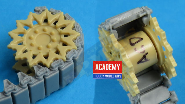
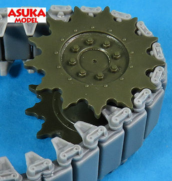
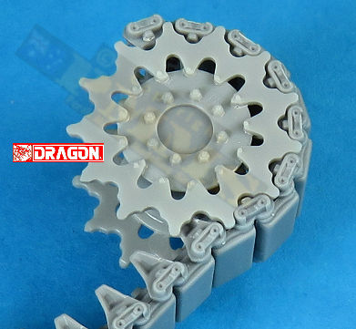
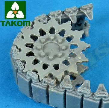
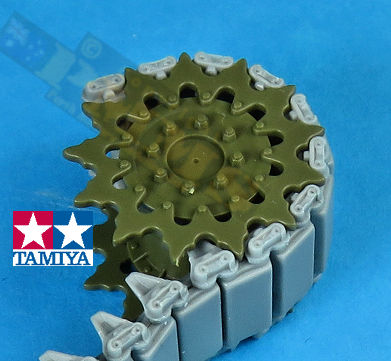
I also test fitted the assembled tracks to other available M3/M4 kit drive sprockets, these included kits from Academy, Dragon, Takom and Tamiya. All fitted perfectly except for the Academy sprockets which were about 1mm too narrow and had to be widened, see image showing the spacing needed. This will allow you to use these tracks on any of these kits you may wish to enhance the detail over 'rubber band' tracks.
The assembly process allows you to either assemble the tracks as workable of glued together solid with the end connector pin design aiding in keeping the links aligned and spaced correctly. The inclusion of an assembly jig would have been helpful but making one up from plastic card and strip isn't that hard and aids with the whole process. The detail on the assembled track runs is very good and adds to the overall look and feel of the kit, making the time spent worthwhile IMHO.
This set can be used an any of the available M3/M4 kits to add detail definition for a relatively inexpensive track upgrade.
Rating 9/10
Son of Sherman Vol.1 Design & Development Ampersand Publishing  |

Thanks to
Please to help the reviews continue, thank you
