
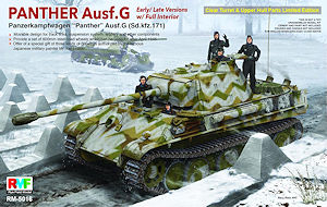
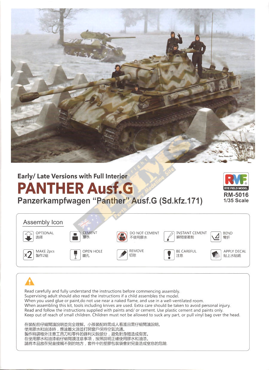
Panther Ausf.G Early/Late w/full interior (Sd.kfz.171)
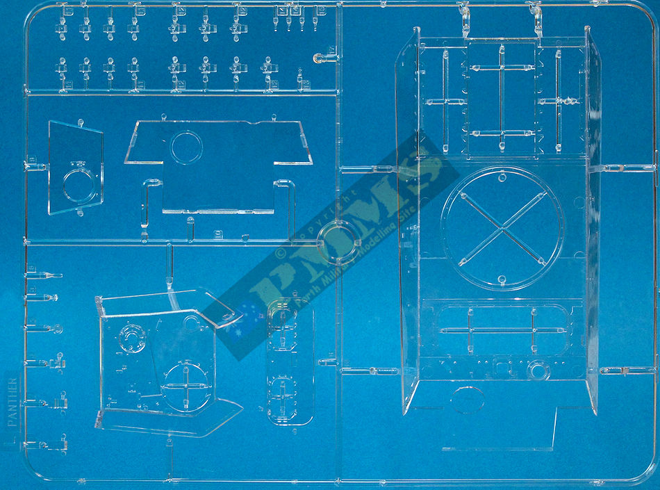
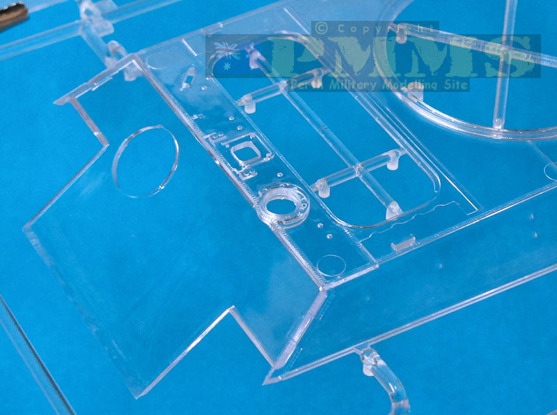
Clear Turret & Upper Hull Parts
Rye Field Model kit RM5016
Review by Terry Ashley
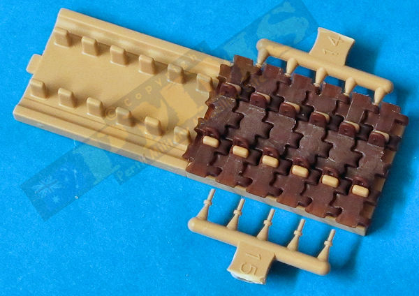
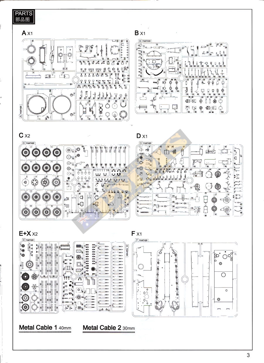
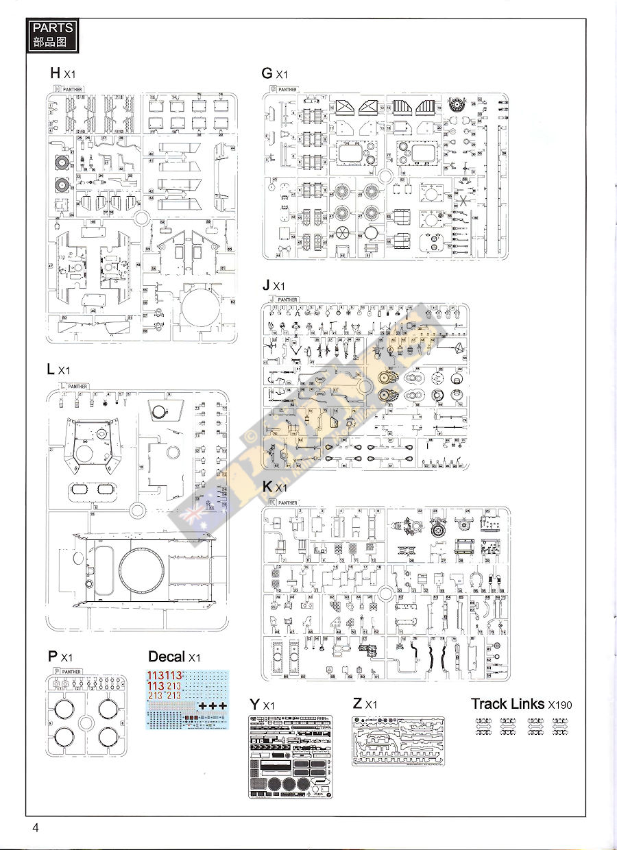
The kit is moulded in light beige and clear plastic with dark chocolate coloured plastic for the individual track link parts with the full kit consisting of:
- 1543 Parts in light beige plastic (includes 190 individual track pins)
- 190 x Individual track link parts in dark chocolate plastic
- 32 x Clear plastic parts
- 18 x black vinyl parts
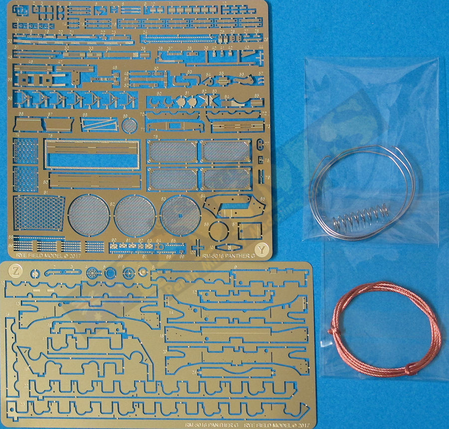
- 196 x Etched metal parts (on two frets, different thickness brass)
- 2 x Lengths of metal wire
- 1 x large metal spring
- 1 x Decal sheet
- 1 x 52-page colour A4 instruction booklet
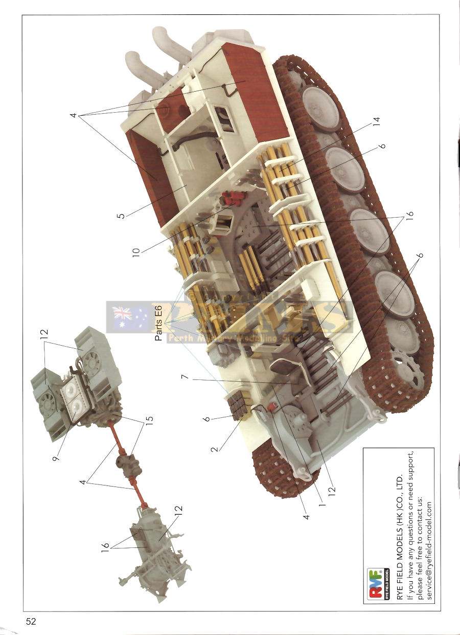
This is a limited-edition kit which features clean plastic upper hull and turret shells to display the interior if you wish?
- Lower hull width/length/access port positions.
- lower hull sides length/height and suspension spacings.
- Upper hull width/length and drivers panel position/engine deck size, hatches, intakes, grill sizes and positions.
- Glacis and Rear hull plate width/height.
- Drive Sprocket/Road Wheel/Idler diameters.
- Track width and pitch/front fender width.
- Turret shell outer dimensions.
- Turret front/Rear plates.
- Gun Mantlet/Gun barrel length.
- Commander's Cupola base diameter/hatch size, plus hull crew hatches.
The verdict with every dimension checked to the plans, to quote a famous local sporting commentator "millimetre perfect". Any differences in dimensions to the plans was in the smallest fractions of a millimetre range which makes for an excellent place to start.
With the option of early or late Gs there are obviously some optional parts in the kit and these include;- Full set of rubber tyred road wheels plus two steel road wheels to use on the first station if you wish.
- Larger and small diameter Idler wheels
- Early single pipe exhaust with round armoured guards, later Flamm exhaust with a choice of rounded or square armoured guards.
- Two styles of engine deck low profile cooling air exhaust armoured guards plus the later raised exhaust duct for crew compartment heating.
- Standard rear plate storage bins with X stamping plus M.N.H bins in April 1945 with vertical ribs. Also included is the smaller right side plain bin used to store IR equipment if fitted?
- Two styles of glacis cast armour guard for M.G.34 ball mount.
- Alternate Glacis plates, one with the early square cut-out and one for with the round cut-out for the driver's periscope.
- Two styles of gun mantlet, early rounded and later chin mantlet.
- Alternate central engine access door with and without heating duct access.
- Alternate inner engine compartment firewall with and without heating duct access.
The standard of moulding is excellent with virtually no flash or pin marks visible after assembly although there is a little excess flash on the inside of the road wheel mountings which is easy to trim off. There are also the usual mould lines to be removed, there are quite a few of the excess moulding nodes on the parts, but noticeably a lot less that on some contemporary kits these days.
There is a slight exception with the pin marks as the clear parts which by their very nature show what's inside and there are some to be seen inside the hull and turret shells. But Rye Field has kept these quite shallow as far as pin marks go with eight inside the main hull and four inside the turret shell but two of these are hidden under small roof brackets leaving just the one to deal with. The other clear parts; glacis, driver's roof panel and rear turret wall are all clear of any pin marks.
There are many small and delicate parts that need care in removing from the parts runners and during assembly but nothing that is out of the ordinary today. The two etched brass frets are of different thickness with a thinner one with all the "usual" PE parts included with kits such as the engine deck screens and many small details around the kit while the thicker fret has the lower hull internal ribs and strengthening brackets.
Note; this is just a brief look at the kit contents with comments and notations on the details to hopefully give you an idea of what's in the box and not an in-depth analysis of any issues or not at this stage.
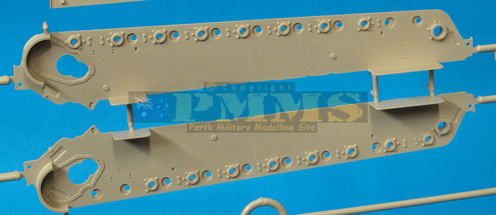
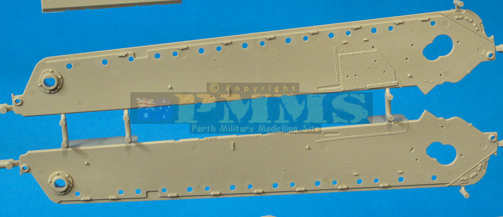
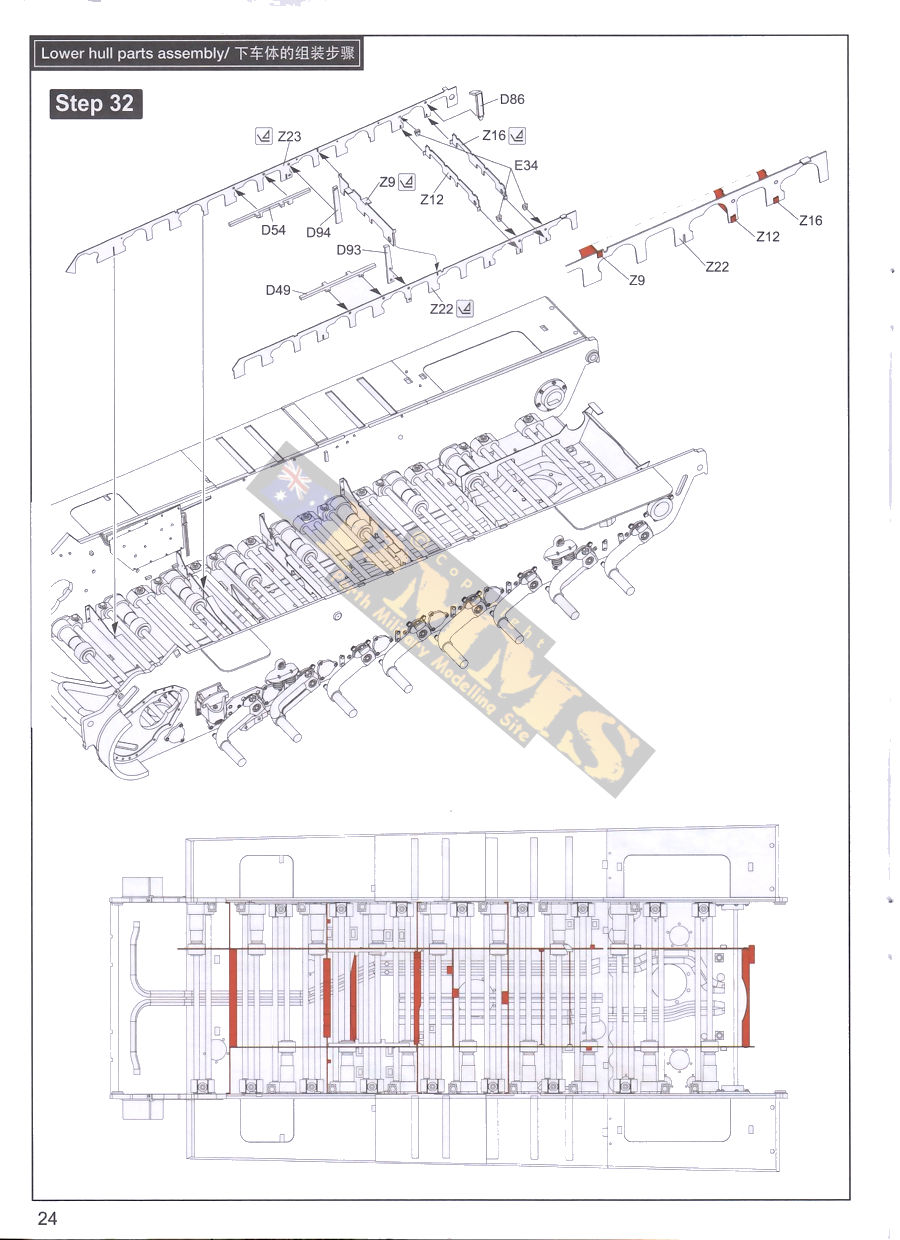
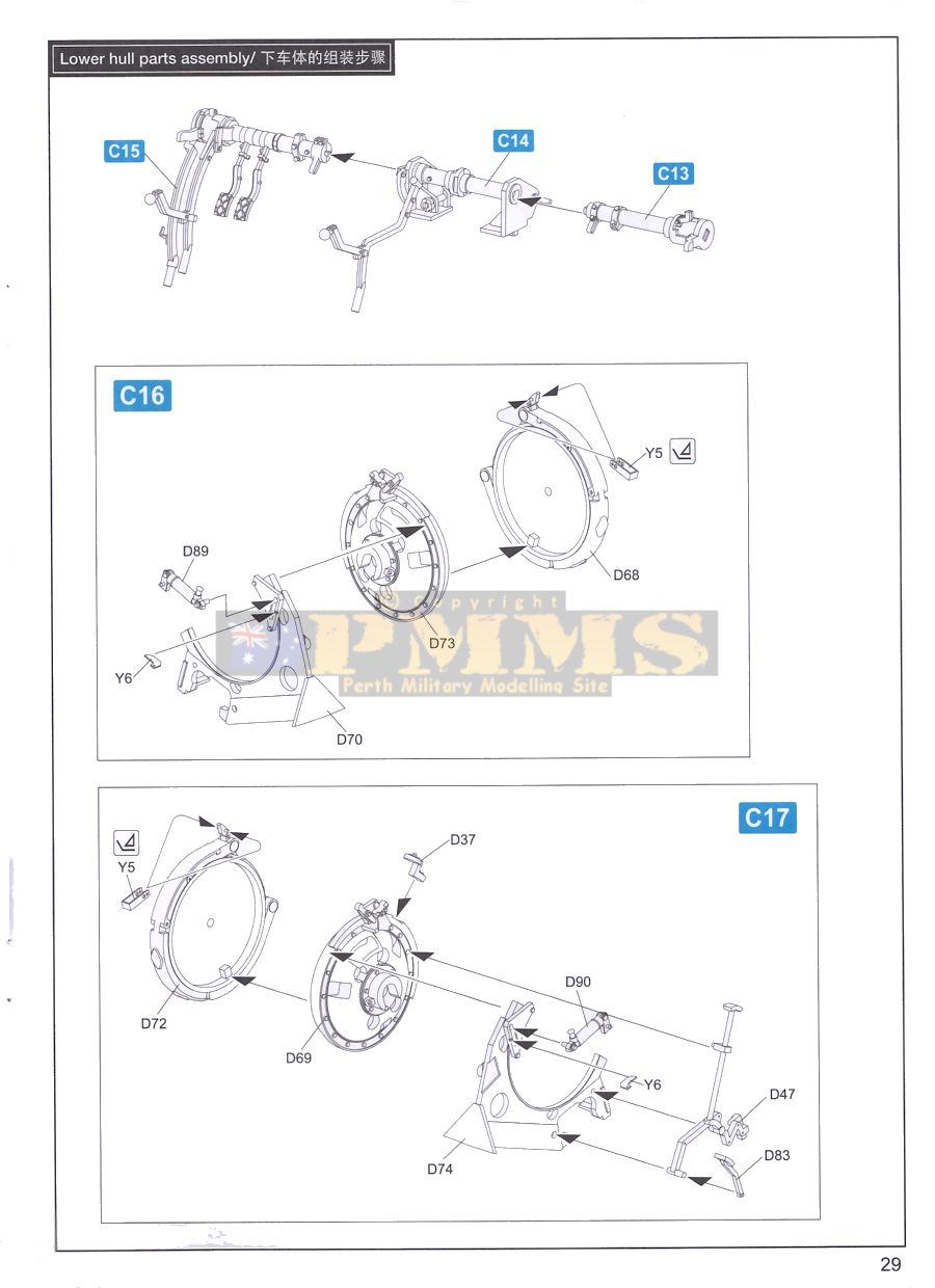
The inside is very busy with the separate torsion bar brackets plus the numerous etched ribs and brackets but the instructions are very clear with additional plan views showing the correct alignment of the bar brackets and PE ribs so there shouldn't be any problems but careful study of the instruction and care would be a good option.
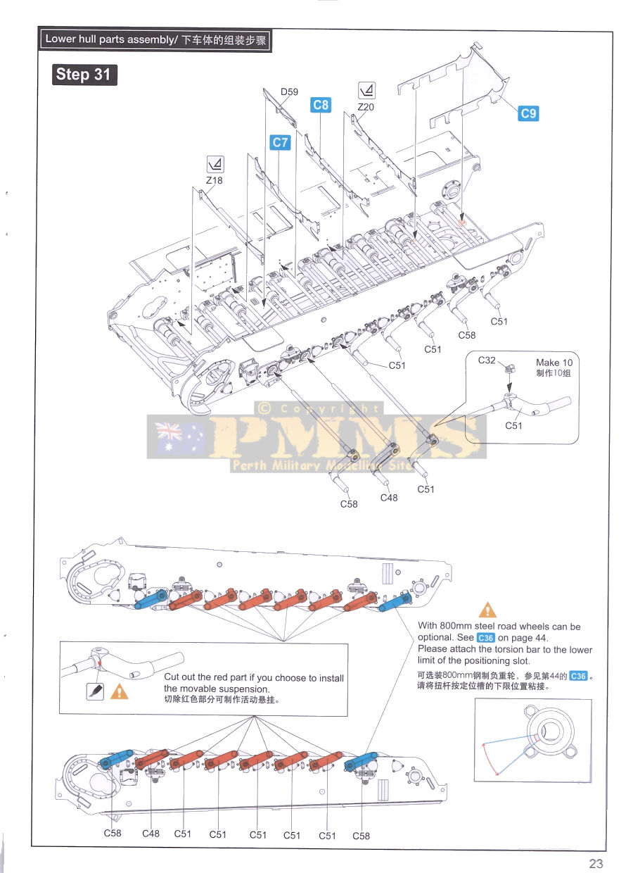
The torsion bars have the road wheel swing arms attached and there are small tabs on the back of each swingarm to locate these at the optimum ride height position, if you want to articulate the suspension simply cut off the tab and position the swingarms at any angle you wish?
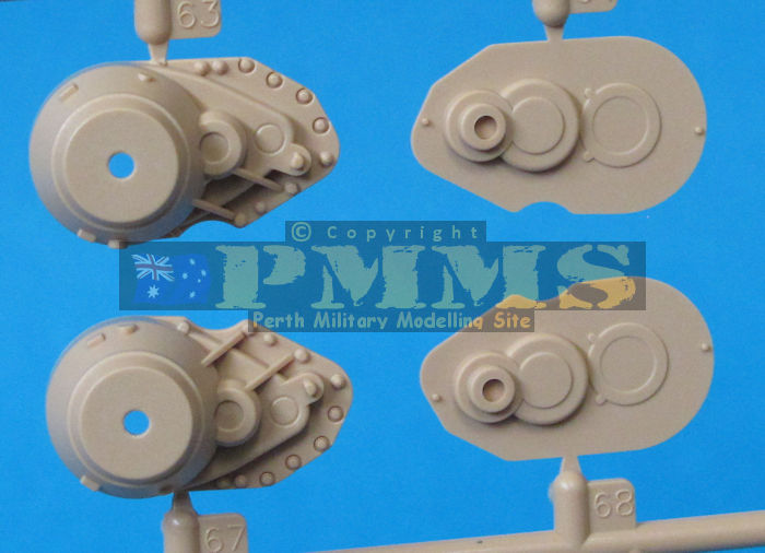
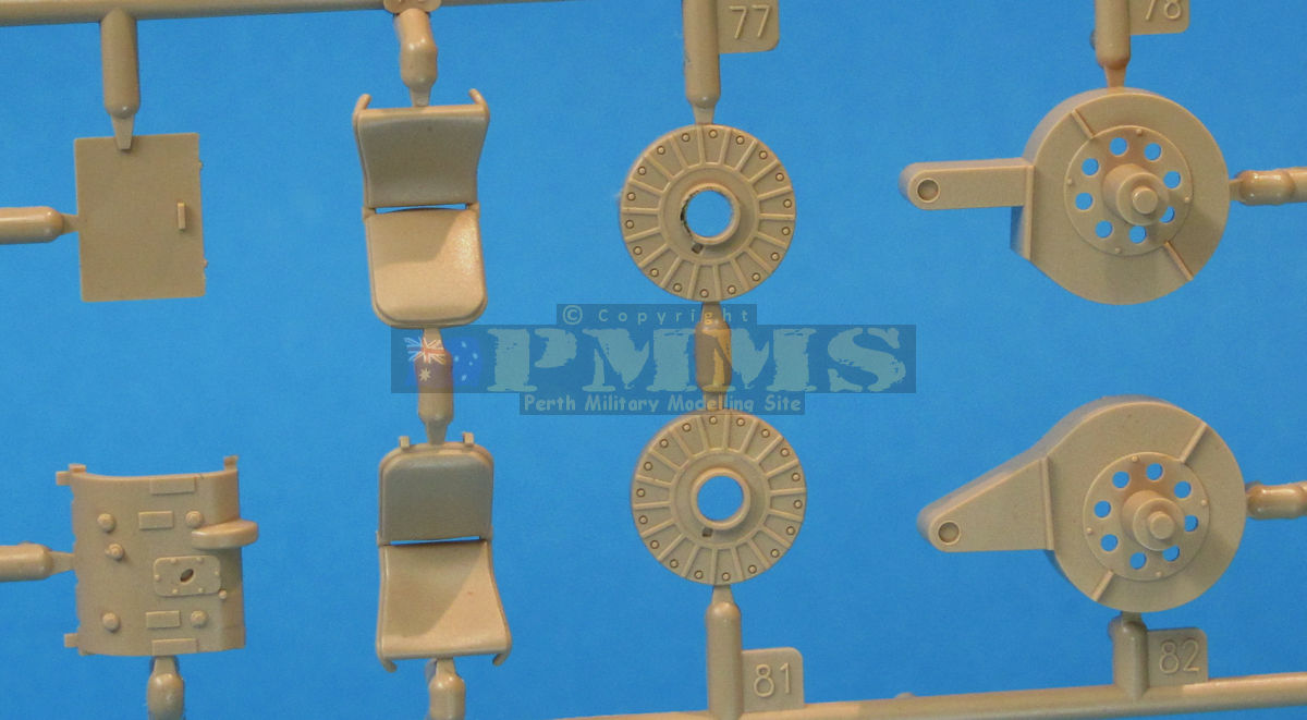
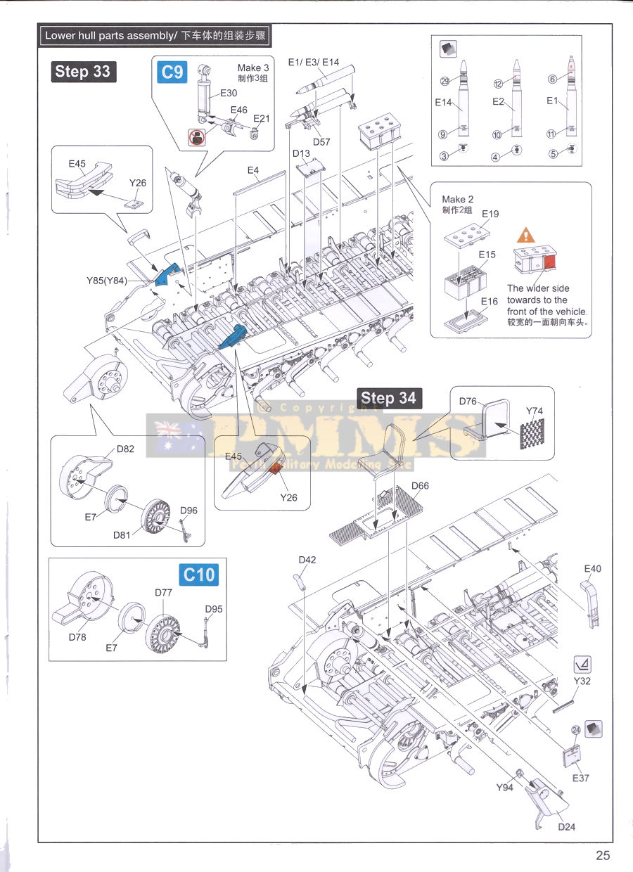
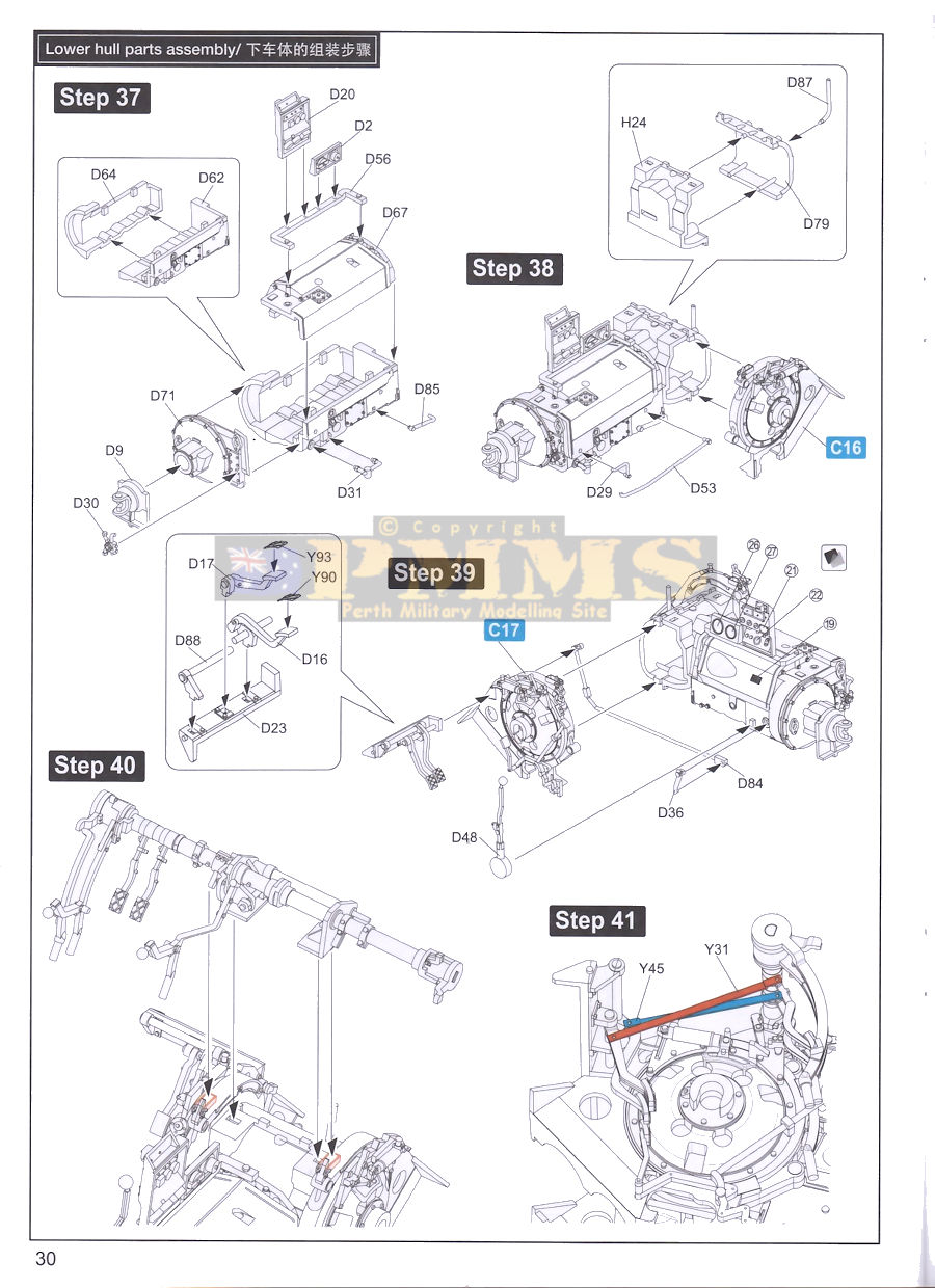
From here the many lower hull details are added that include the inner front wheel shock absorbers, ammo racks and other equipment, the front brake units and the two crew seats that have etched rear seat springs included. There are quite a few items but again the instructions are quite clear on where things go.
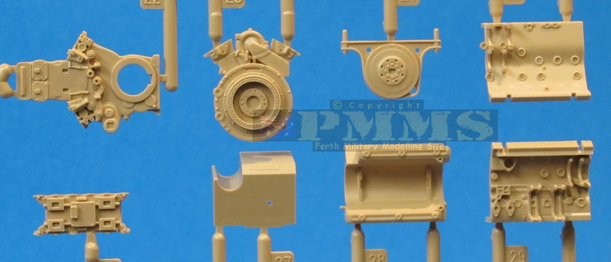
The extensively detailed gearbox/transmission unit is made up of 55 finely moulded parts (plastic and PE) and this is further enhanced with separate fine ducting in moulded plastic and etched rods connecting the foot pedals which in turn have embossed PE faces added. The finesse of the parts on the runners should translate into a very impressive and detailed sub-assembly once assembled and painted.
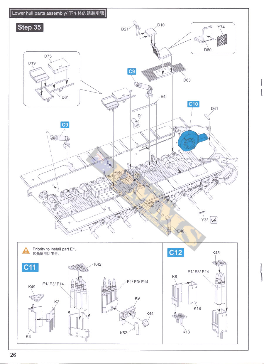
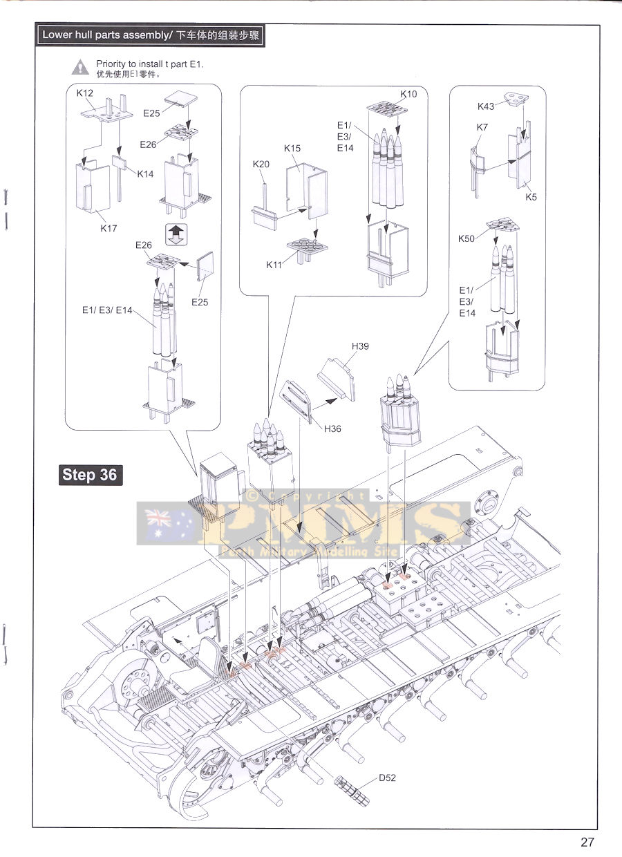
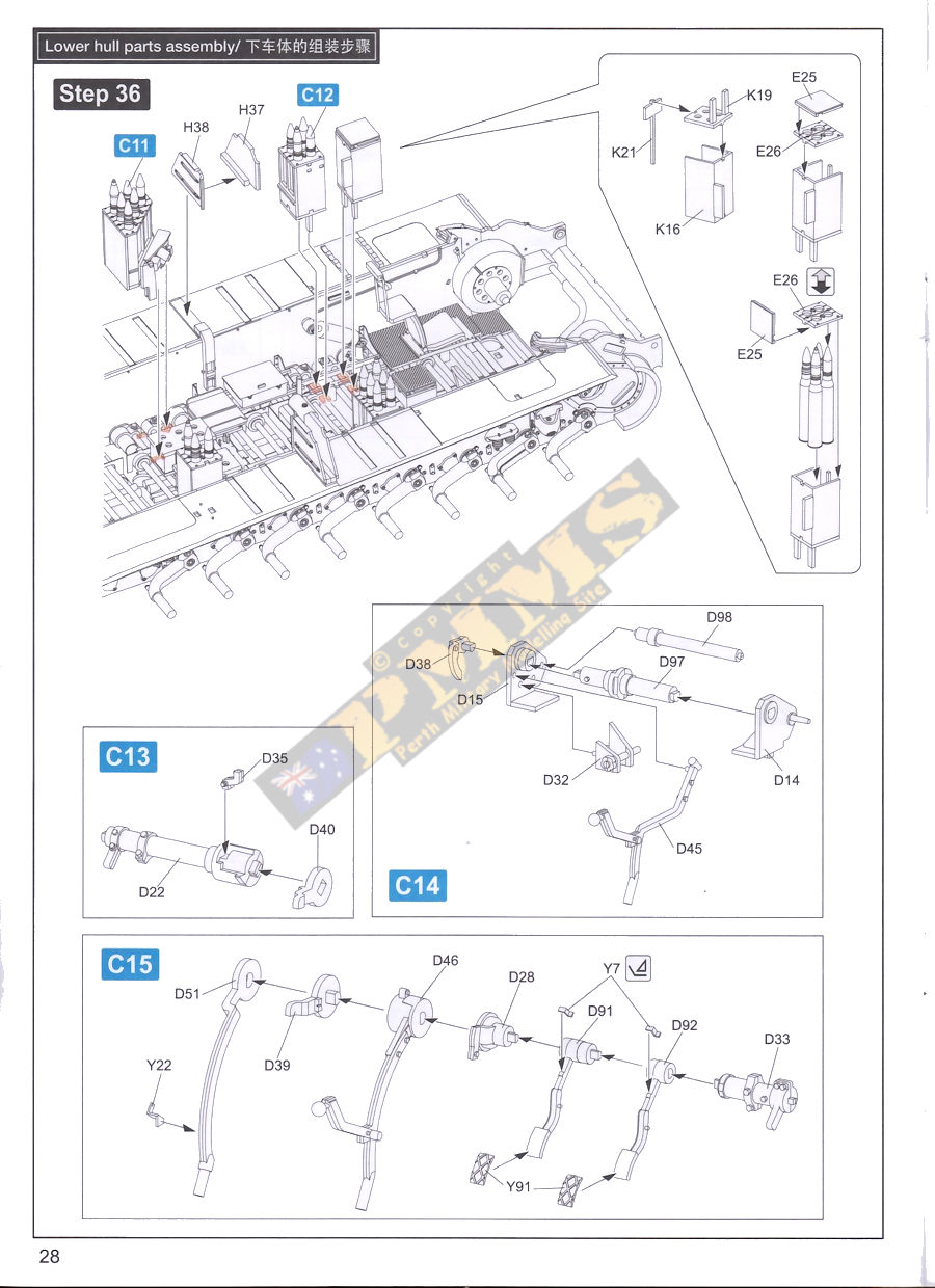
The central square floor section is added plus numerous other items as shown in the instructions before we move up the supporting bulkhead added centrally between the sponsons as well as the large ammo racks on the sponsons each with individual 75mm rounds and finely moulded rack clips.
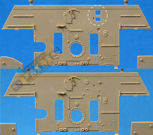
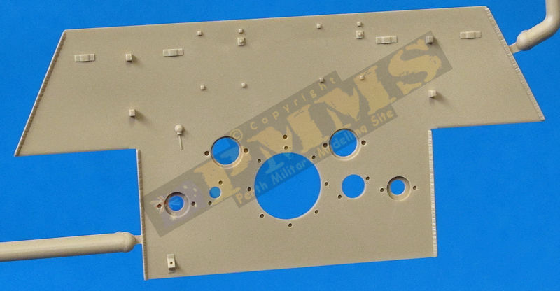
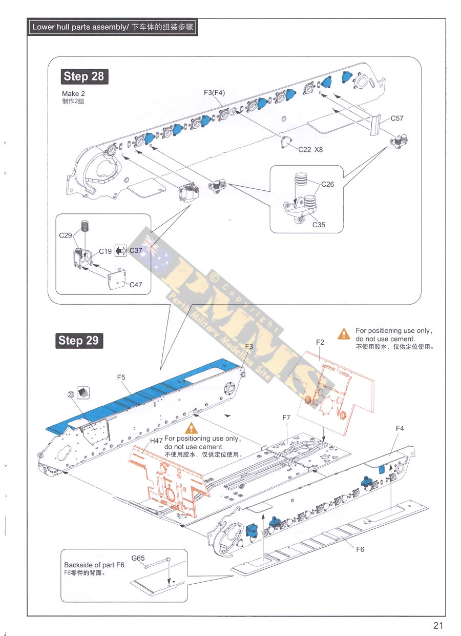
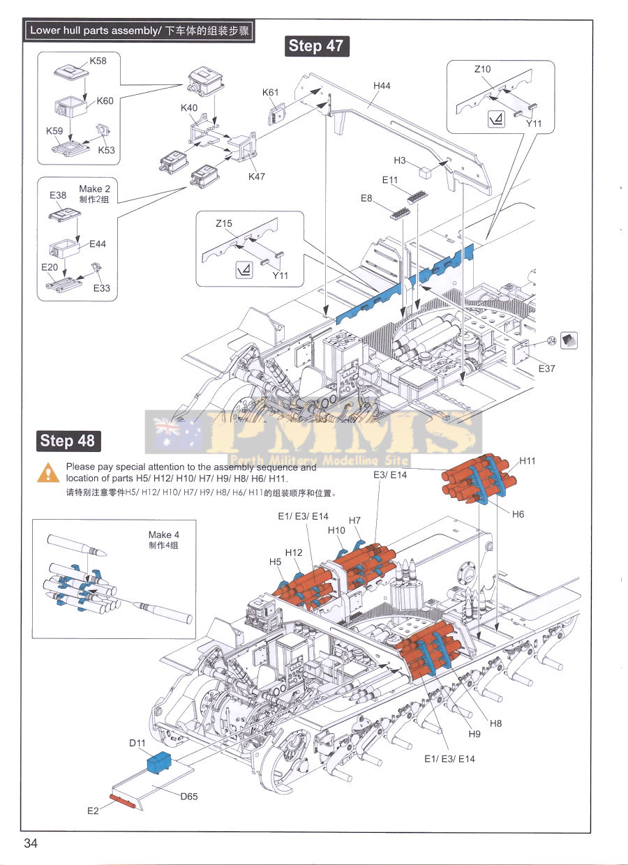
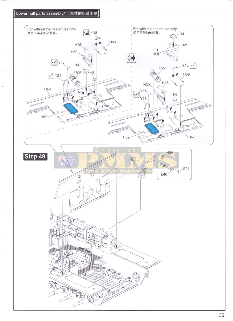
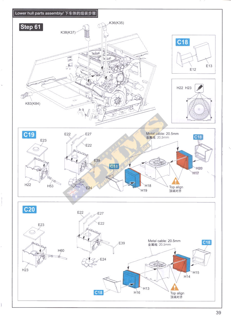
Moving back is the engine compartment firewall-bulkhead with nice surface details included to which is added additional detail items, there are actually two bulkheads provided, one for the early version (H48) and the other with cut-outs for the compartment heating system used on later models (H47) so you choose the appropriate one for the model you are building. Also added in the engine compartment are the two inner shock absorbers for the last wheel station as well as the engine compartment sectional bulkheads.
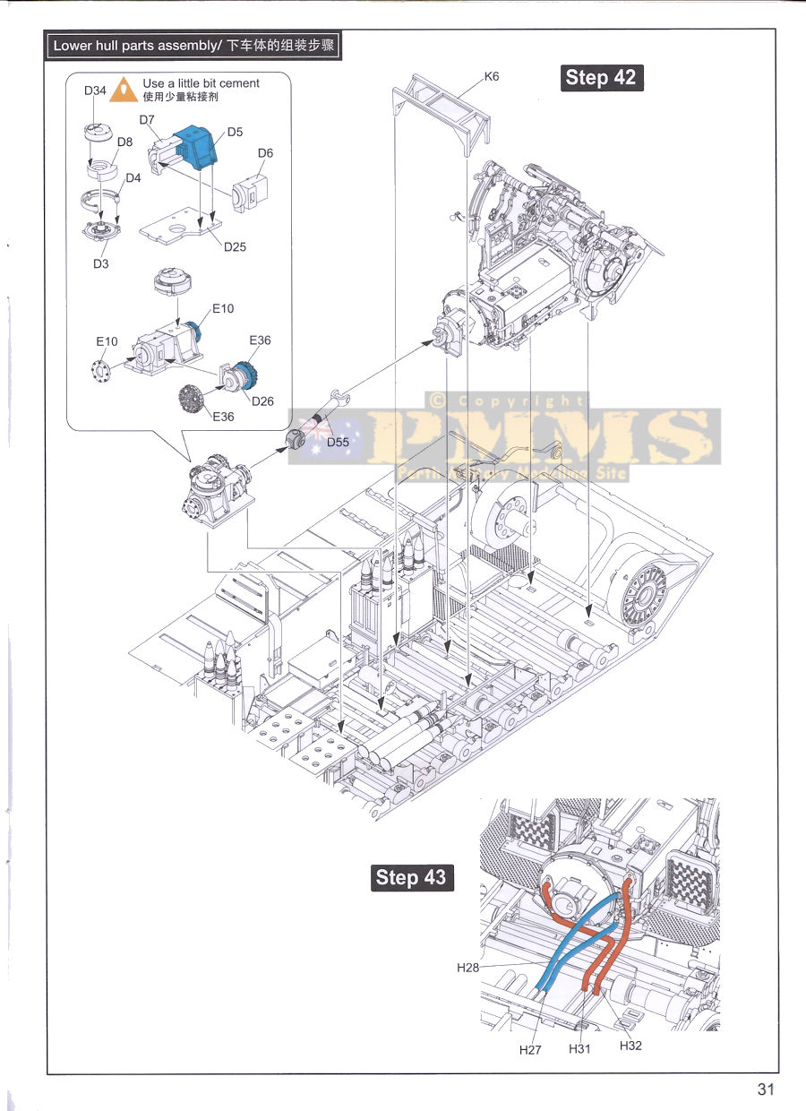
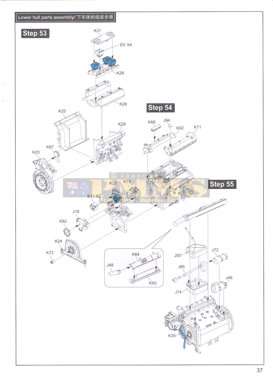
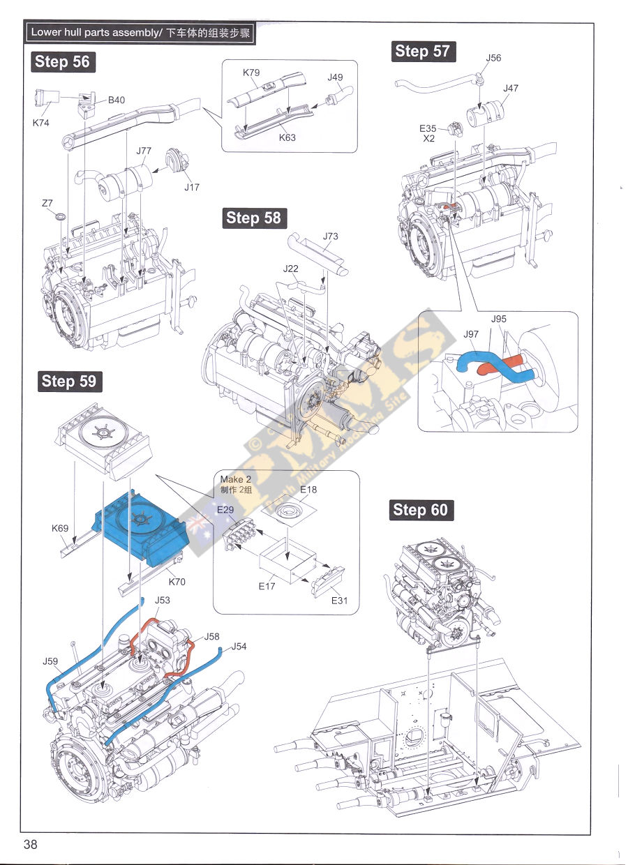
The Maybach HL 230P30 V-12 engine is another superbly detailed sub-assembly, the main engine parts have nice crisp well defined details included with all the major engine accessories provided as separate parts, 48 in total for the engine plus another 10 for the twin fan unit that sit on top of the engine assembly. This is supplemented by additional plumbing provided in moulded plastic as well as the metal wire provided and again should assembly into an impressive engine assembly. The instructions include two plan view illustrations from the rear and overhead to clearly show the positions of the piping and wiring to avoid any confusion.
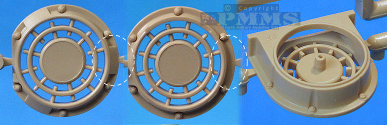
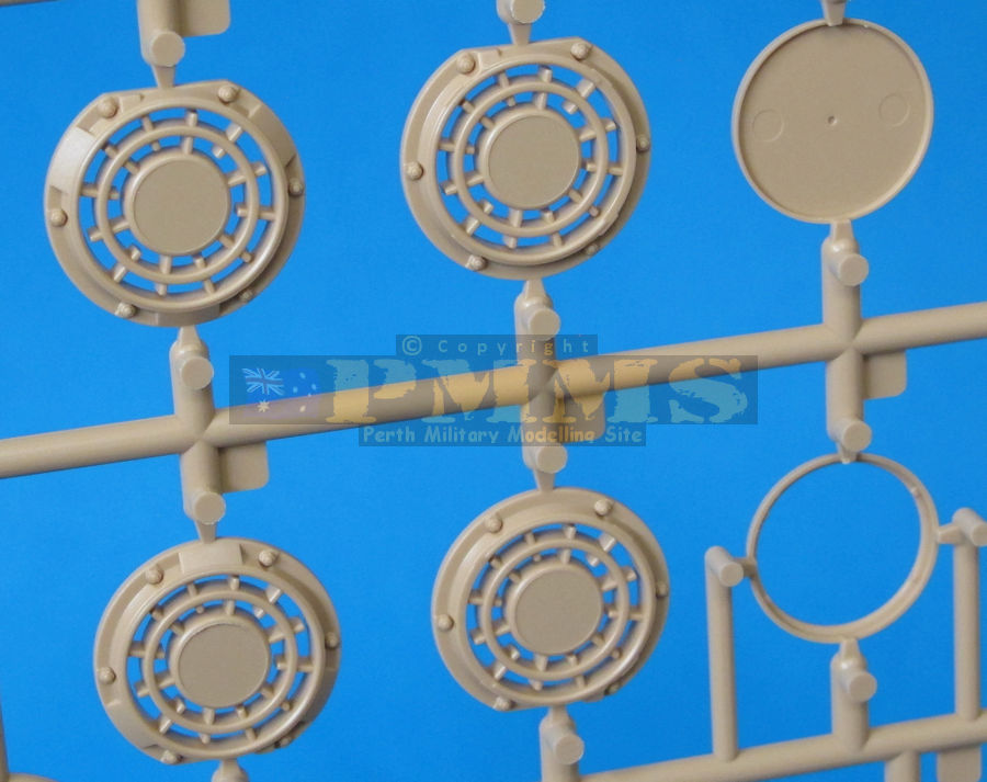
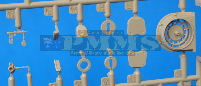
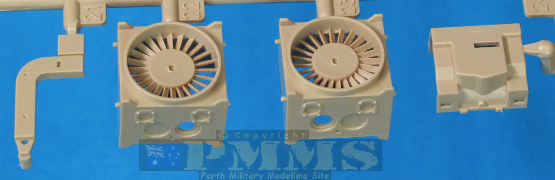
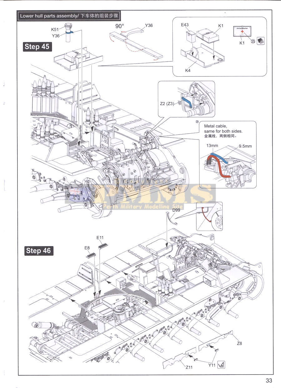
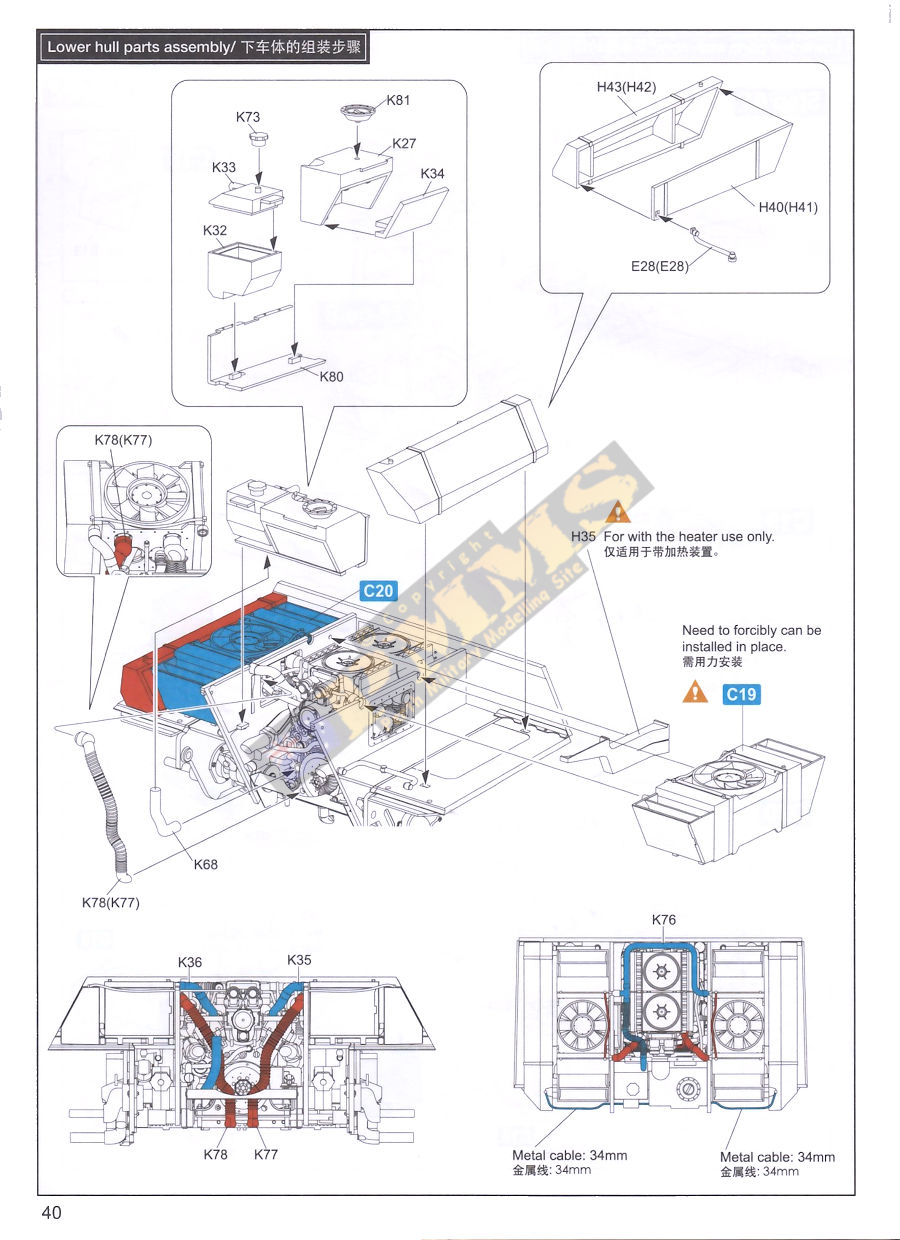
In the side sponson compartments are the two fan/radiator units made up of 12 parts each plus thin metal cables between the radiators, the actual fans are separate parts for excellent detail definition on the assembled units. The fuel tanks are also nicely detailed and once the fuel tanks, fan/radiator units and engine are fitted into the hull there are addition large pipes moulded in plastic that go between the radiators and engine as well as fuel lines from thin metal cable to complete the overall assembly.
As mentioned the road wheel swingarms are incorporated with the torsion bars fitted earlier and have nice details incorporated as well as having the three differently shaped and detailed swingarms as fitted on the 1stand either 7th/8th stations (C58), 2nd station (C48), 3rd to 6th station plus either 7th/8th stations (C51). Take careful note of the assembly sequence in Step 31 to ensure you fit the correct swingarm to the correct suspension station.
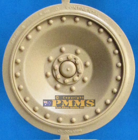
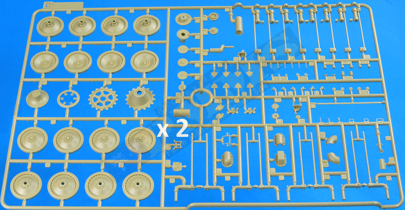
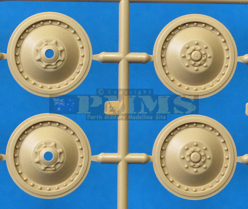
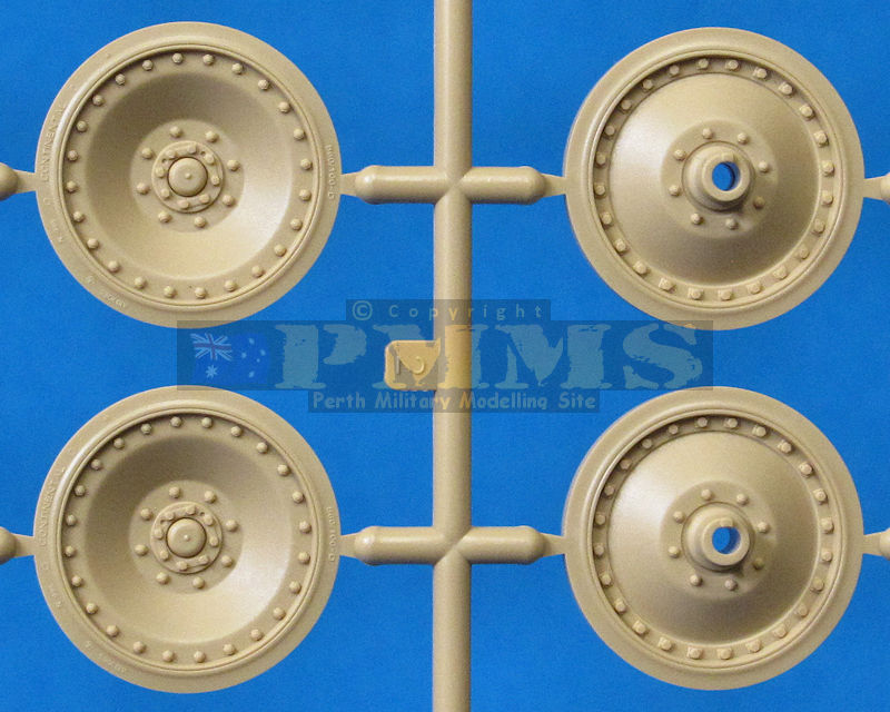
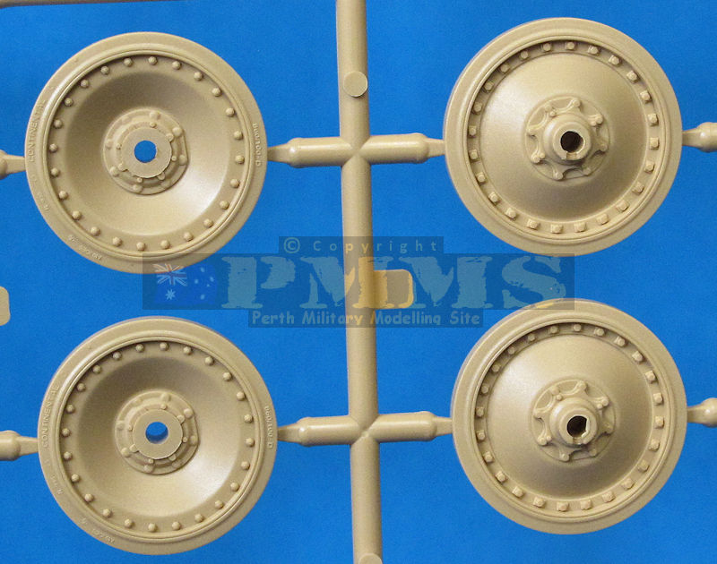
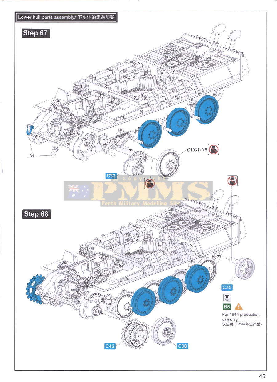
The road wheels are moulded entirely in beige plastic and are also nicely detailed with the correct 24 outer rim bolts and straight bolt retaining strips on the hub bolts, the outer tyre sections include the tyre data embossing and the name CONTINENTAL cleanly embossed on the sidewalls. The central pairs of wheels join together trapping a poly cap between them for attaching to the axle stub while the inner wheels are simply slipped into the axle stubs and held in place by the central pair and the outer wheel is then glued to the inner wheel hub with the instructions indicated to rotate the inside and outside wheels until the glue 'goes off' leaving the wheels to rotate freely while still being glued to each other.
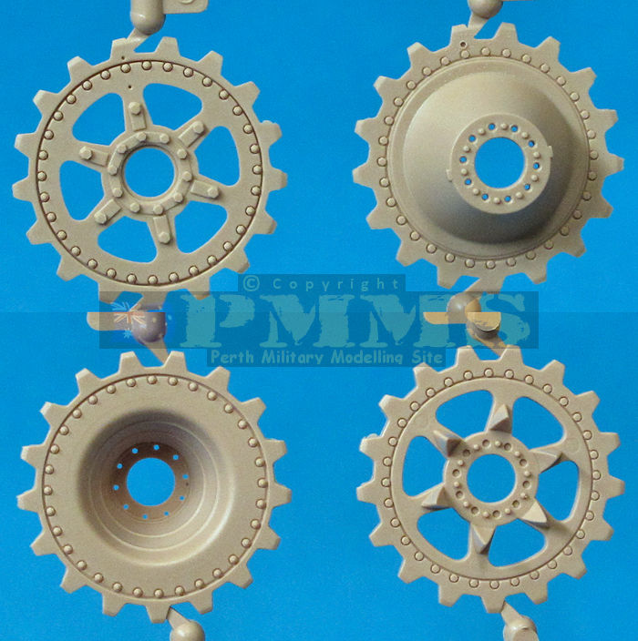
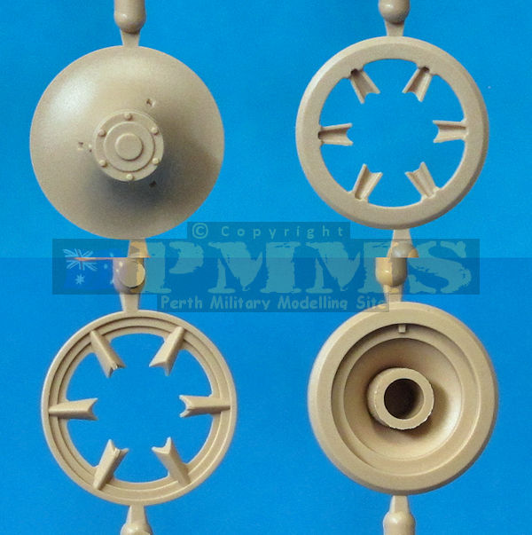
There are alternate larger and smaller diameter Idler wheels included with three parts for the larger and four parts for the smaller idler to give excellent detail definition, both trap a poly cap inside for fitting the idler swingarm which can be mover to alter the track tension as required.
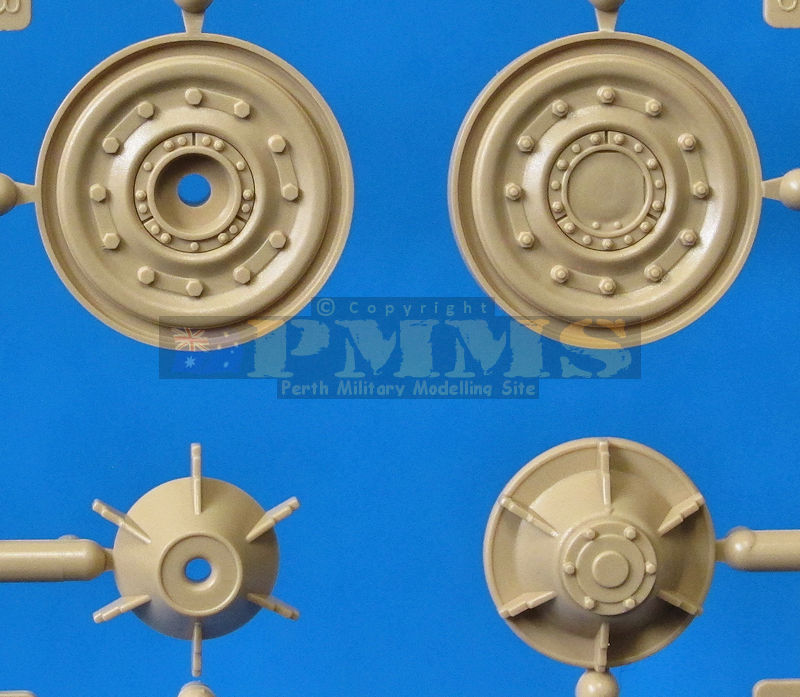
Also included are two sets of later steel road wheels to use on stations 1 or 8 if the vehicle you are building has these fitted, the detail of steel wheels is also nicely done. Note, you have to slightly alter the position of the swingarm if fitting the steel road wheel with the instructions indicating this.
Also included are three spare road wheels that have separate inner and outer hub parts to provide a higher level of hub detail than the wheels fitted to the running gear. The tyre sections are also separate vinyl with sidewall embossing included and the spares can be used where ever you wish on the model or as extras in a diorama.
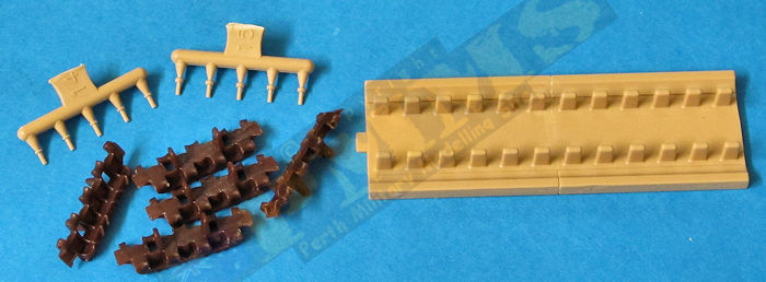
Track links on the jig with pins inserted, repeat for more links.
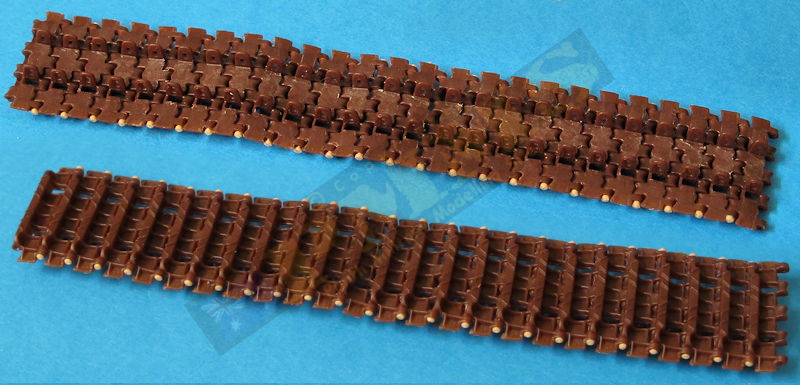
Lengths of track with pins cut from runners.
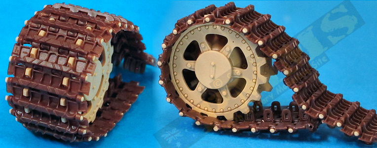
Tracks around the sprocket showing good fit.
You also get some additional cleats to add as you wish along with the track removal tool in etched brass and thin plastic bar should you wish to do a track maintenance diorama, nice additions for sure.
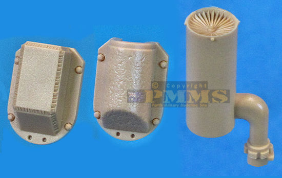
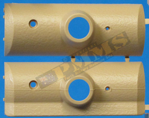
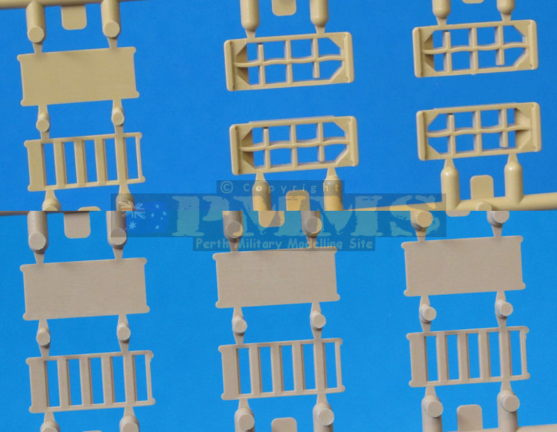
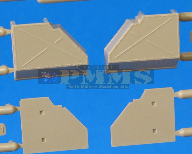
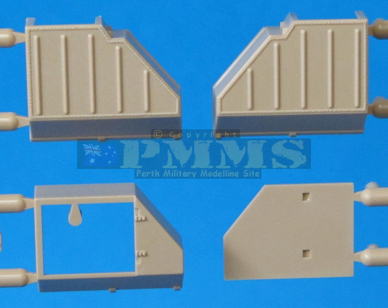
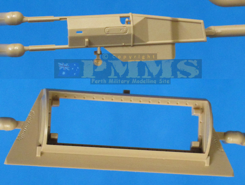
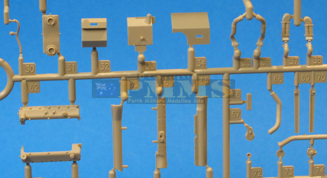
The Jack stowed on the rear plate is made up of eight plastic and four etched parts for quite detailed assembly and there is a choice of three styles of rear stowage bins, the original with the X stamping on the lid, the M.N.H. type with vertical stampings used from April 1945 and the smaller plain bin used to stow IR sighting gear when used by the vehicle. The details on the bins is very well done although the welds appear a little overdone around the edges?

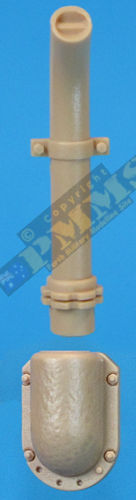
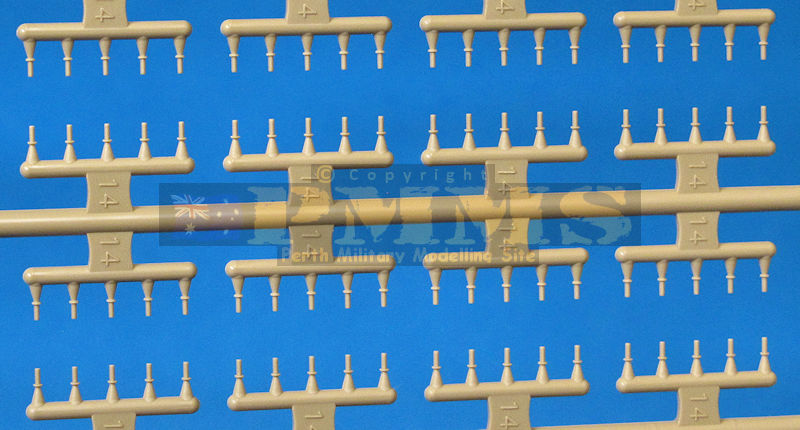
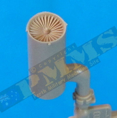
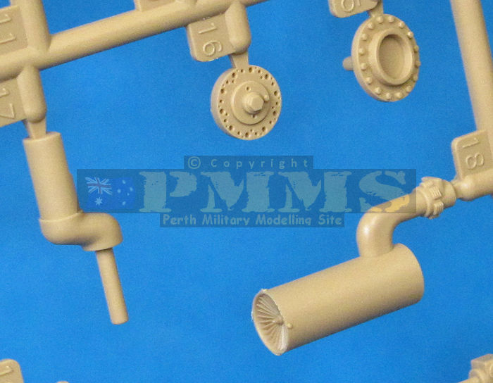
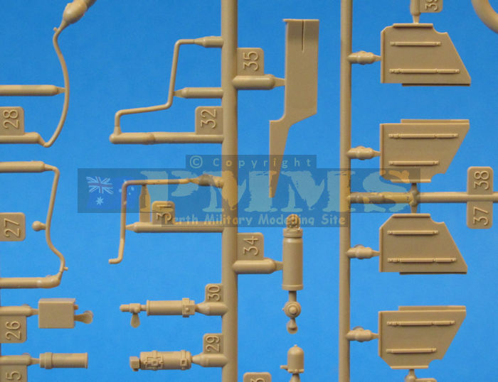
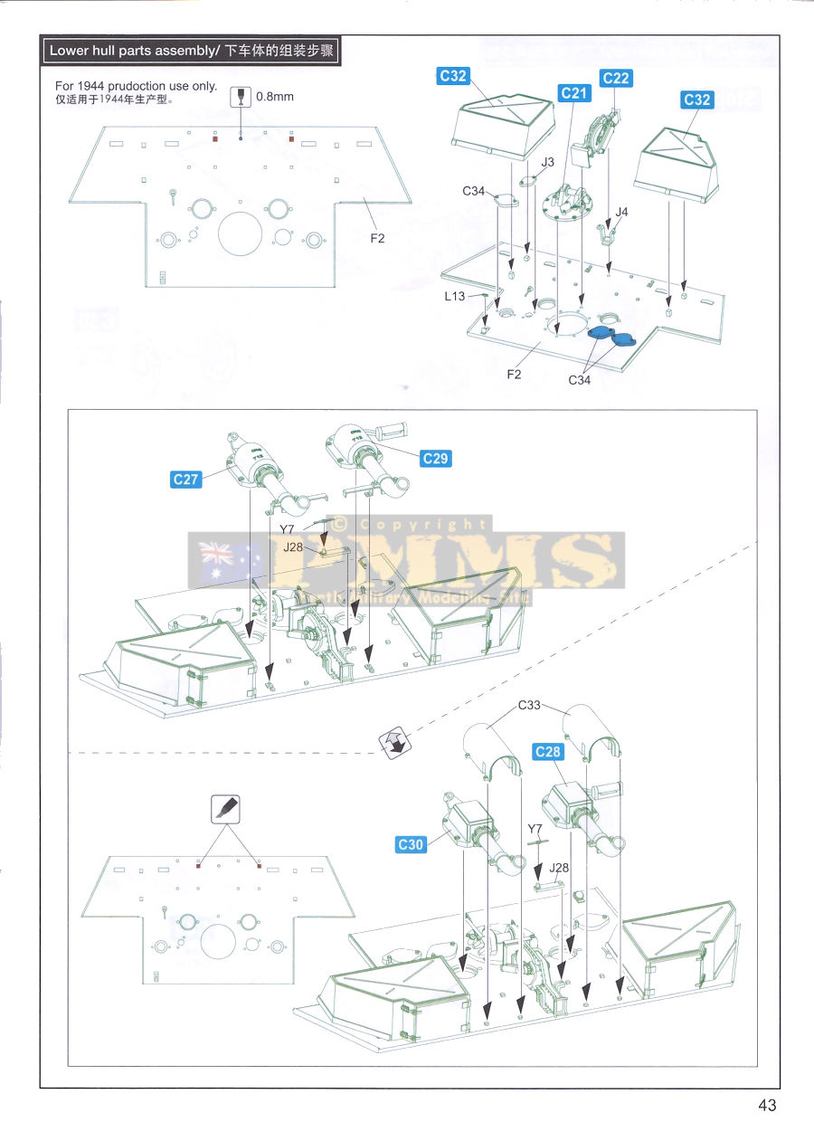
The kit provides parts to build any of five different exhaust configurations with three different style of armour guard included. These are; 1. the original G config of single pipe with cast armour guard, 2. the single pipe/cast guard with sheet metal covers added over the pipes, 3. Single pipe with welded armour guard with sheet metal covers, 4. Flamm muffles with welded armour guards and 5. Flamm mufflers with later style cast armour guard.
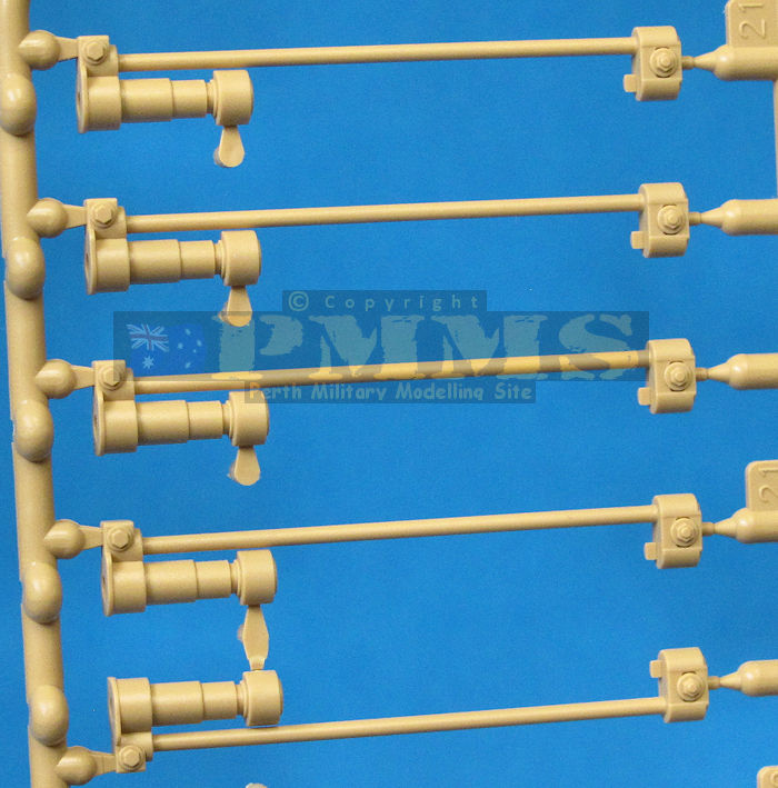
Detail on the exhausts is well done with subtle casting texture on the two styles of cast guards and welds on the joins for the welded guards, with the tops of the single pipes are slightly indented with the thin cross bracket and the fan detail on the tops of the Flamm muffler is quite well defined for a good appearance. The mountings are a combination of moulded on brackets on the single pipes with additional etched brackets on both styles for good detail, there is also the rear tail light that is attached to the left-hand armour guard whichever one you use.
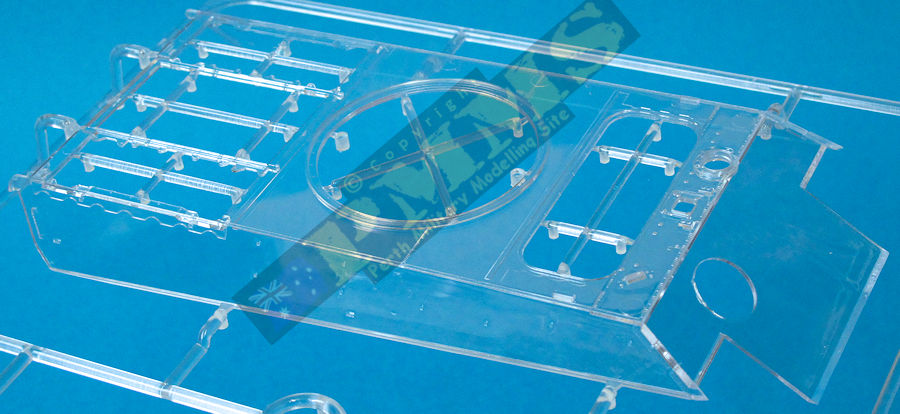
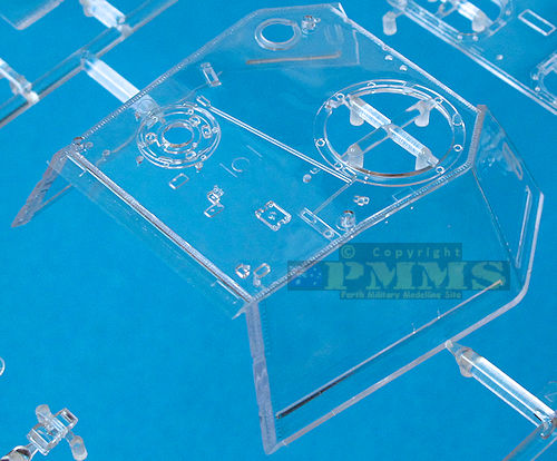
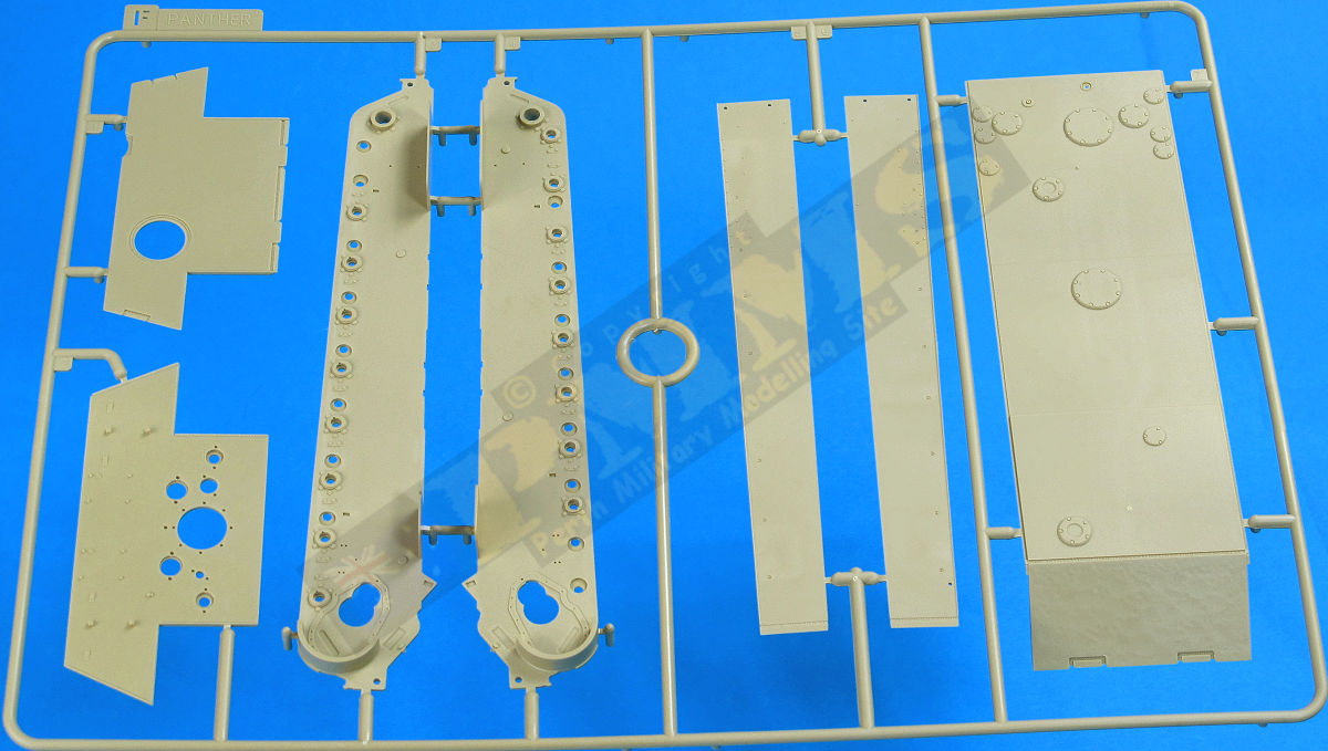
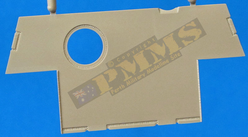
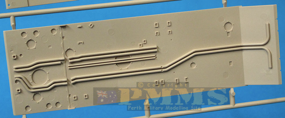
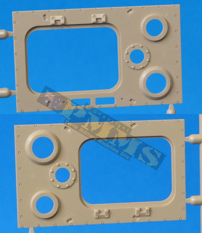
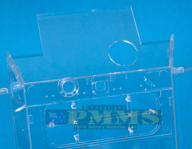
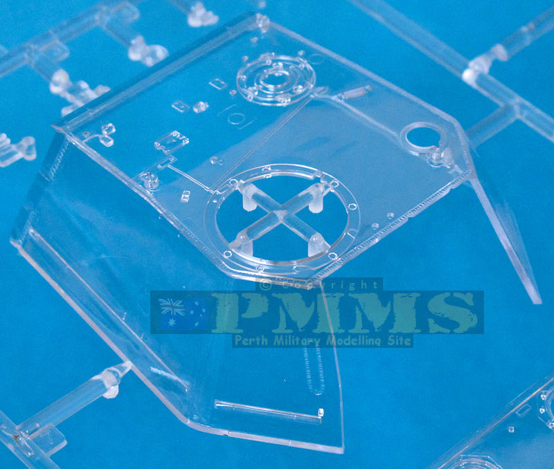
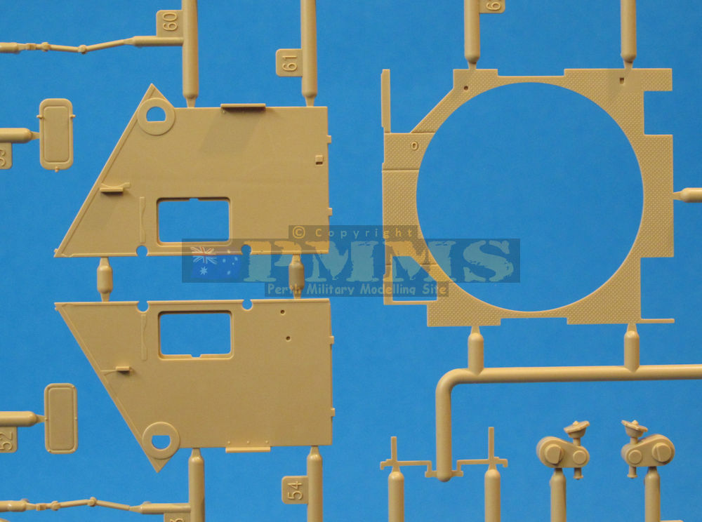
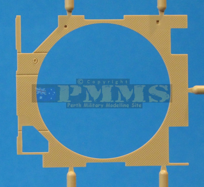
The main hull is moulded in clear plastic as is the separate driver's compartment roof panel and the periscopes with all other parts in normal beige plastic. External detail is restricted to the panel join welds and some screws around the periscope housings. One issue is the fine pin marks showing inside the hull as mentioned above but these hopefully won't take too much to smooth out? The other of course is to be very careful with the glue when attaching the additional parts if you intend to display the model with the clear parts clear?
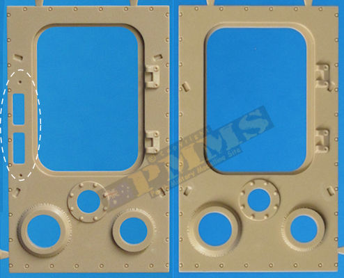
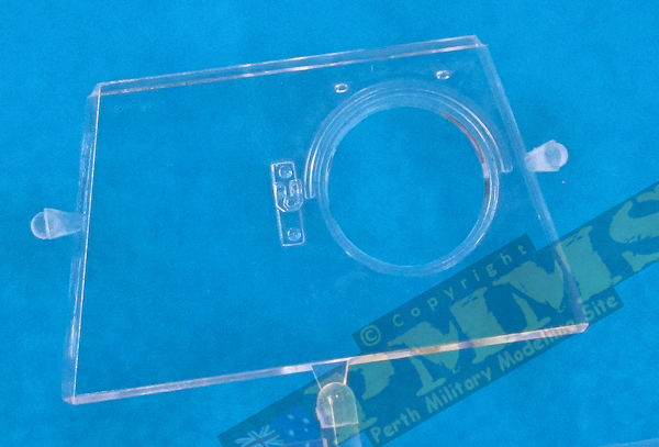
There are two separate glacis plates that attach over the top of the glacis extension on the main hull, the early type with the square cut-out for the driver's periscope in normal beige plastic and one for post July 1944 builds with the round cut-out for the driver's periscope in clear plastic. So, your choice of glacis to use depends on the vehicle you wish to build, early or later types.
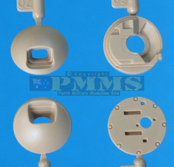
The glacis has the cut-out for the M.G.34 ball mounting and outer cast armour guard, there are two guards in the kit with different style bullet splash ridges and again you choose the one applicable to your model. The inside gun mounting is well done with a two-part M.G.34 with a small section of ammo belt plus the gun cradle, binocular sight and two ammo pouches, this assembly has the barrel fed through the inner mounting plate (J69) and held in place with the outer ball (J10) with the mounting plate glued to the inside of the glacis opening with the ball sitting inside the contours of the outer armour guard for a fully movable gun mounting.
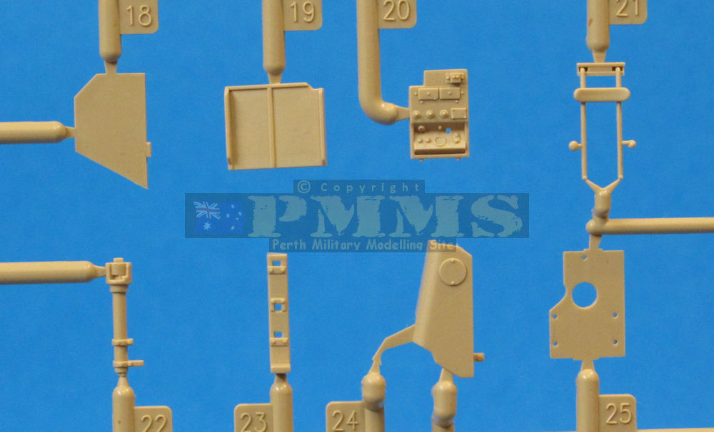
Other items added inside the front hull are the two clear periscopes with PE brackets, four small grab handles and the central radio assembly, this compared to some of the other details is fairly basic with the radios moulded as one with separate back panel. This is glued to the inside of the roof and again care will be needed to minimise glue marks during assembly.
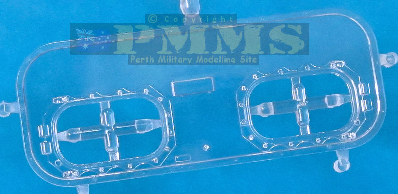
The crew compartment roof is a separate clear part with separate beige plastic doors that can be fitted open or closed and include nice detail such as the latches, inner braces (one for open and another for closed hatches) and outer grab handles.
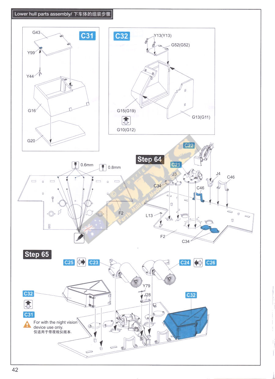
On the outside there are the two periscope guards with alternate guards for the Driver's scope, the initial narrow guard and the later extended sunshield, either guard is attached to the rotating top periscope cover (G28) and care is needed when gluing if you want the fitted periscope/guard to rotate in the hull mounting. Centrally is the vent and cover plus the movable travel lock, this has nice details and alternate plastic simulated barrel securing chain for the open or closed position, the lock can also be fitted in the raised or lowered position as required.
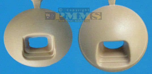
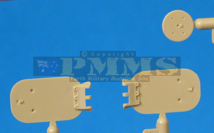
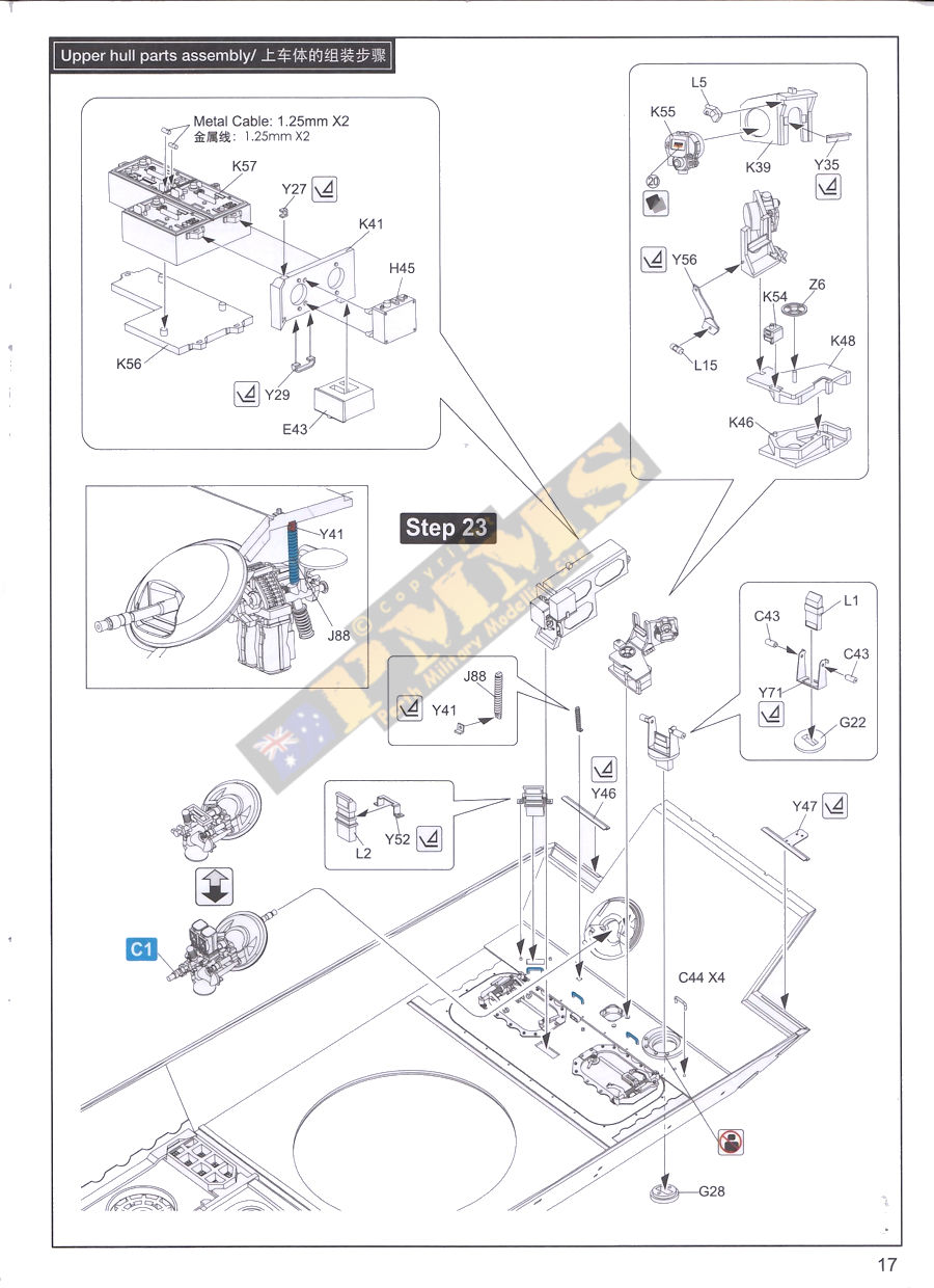
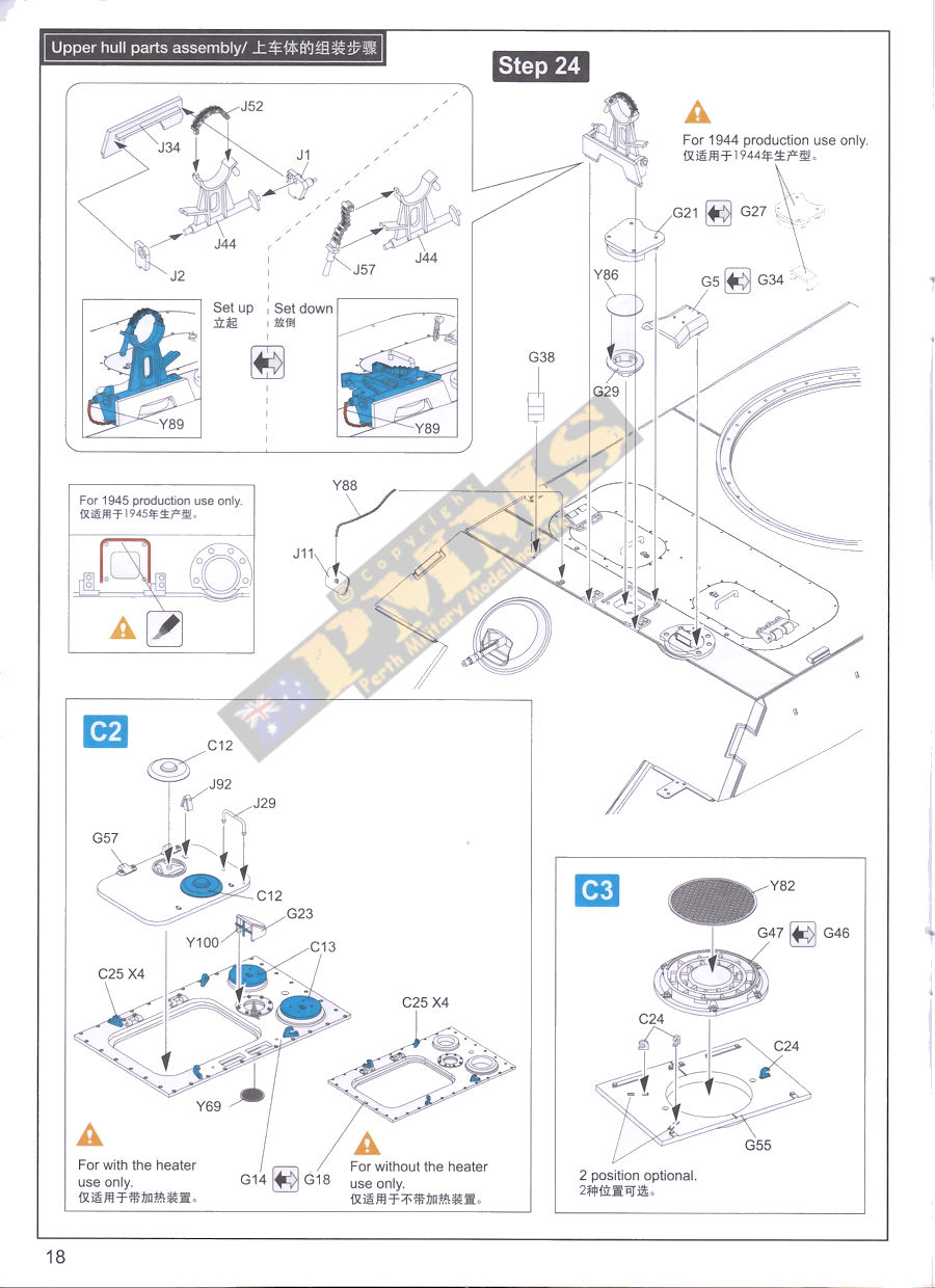
Moving back to the engine deck, there are two alternate central engine deck panels, one (G14) with and one (G18) without the openings for the crew compartment heating. Added to either one is the access door with the two dome vents and grab handle allowing the door to be positioned open or closed as you wish?
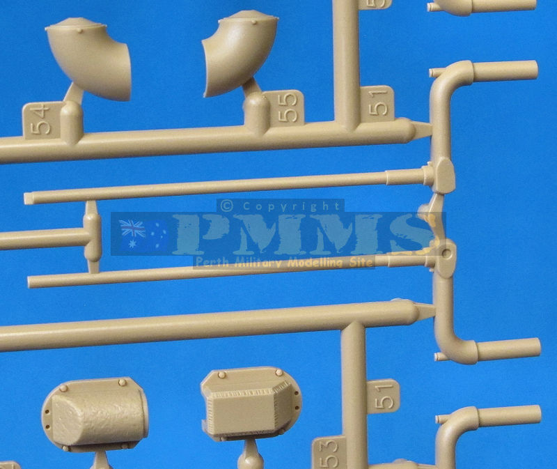
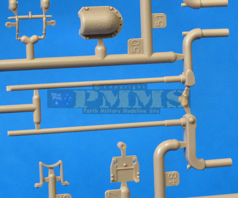
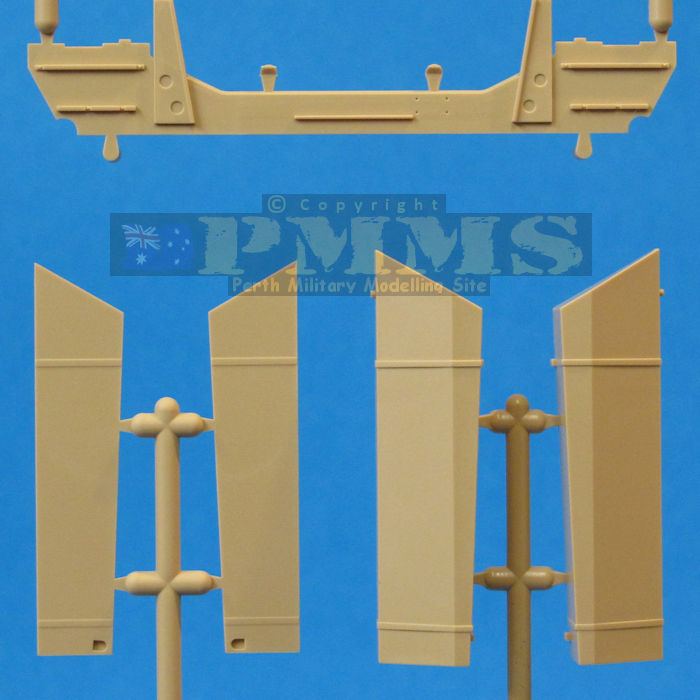
The two side panels consist of the central sections (G55, G56) with alternate low-profile cooling air exhaust armour guards (G46, G47) with PE screens, plus the alternate left side raised armoured crew compartment heater intake with additional section on the central panel and PE screens with the pie-slice guard to close of then intake if required. Either side of the central panels are the rectangular cooling air intake armoured guards with PE screens (G45), also included are the sliding shutter covers (G8, G9) to close off the intakes but note, these should only be fitted to the right-side intakes and not both sides as indicated in the instructions.
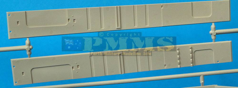
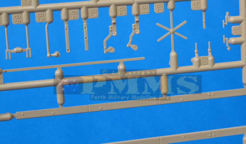
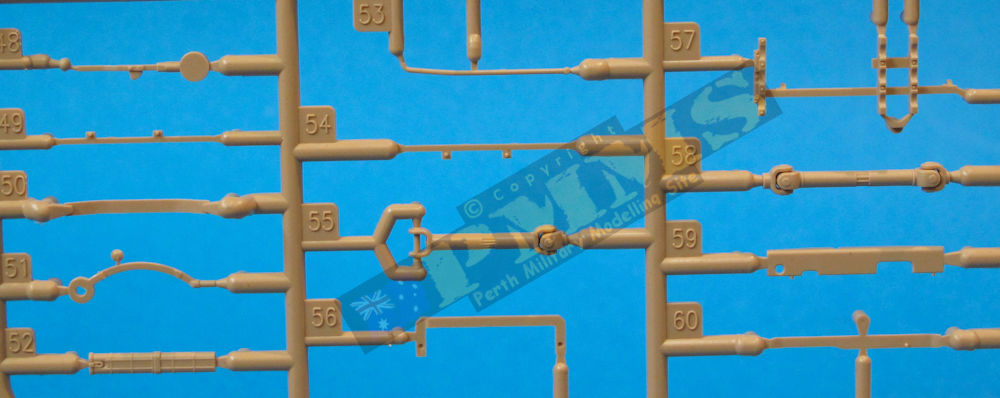
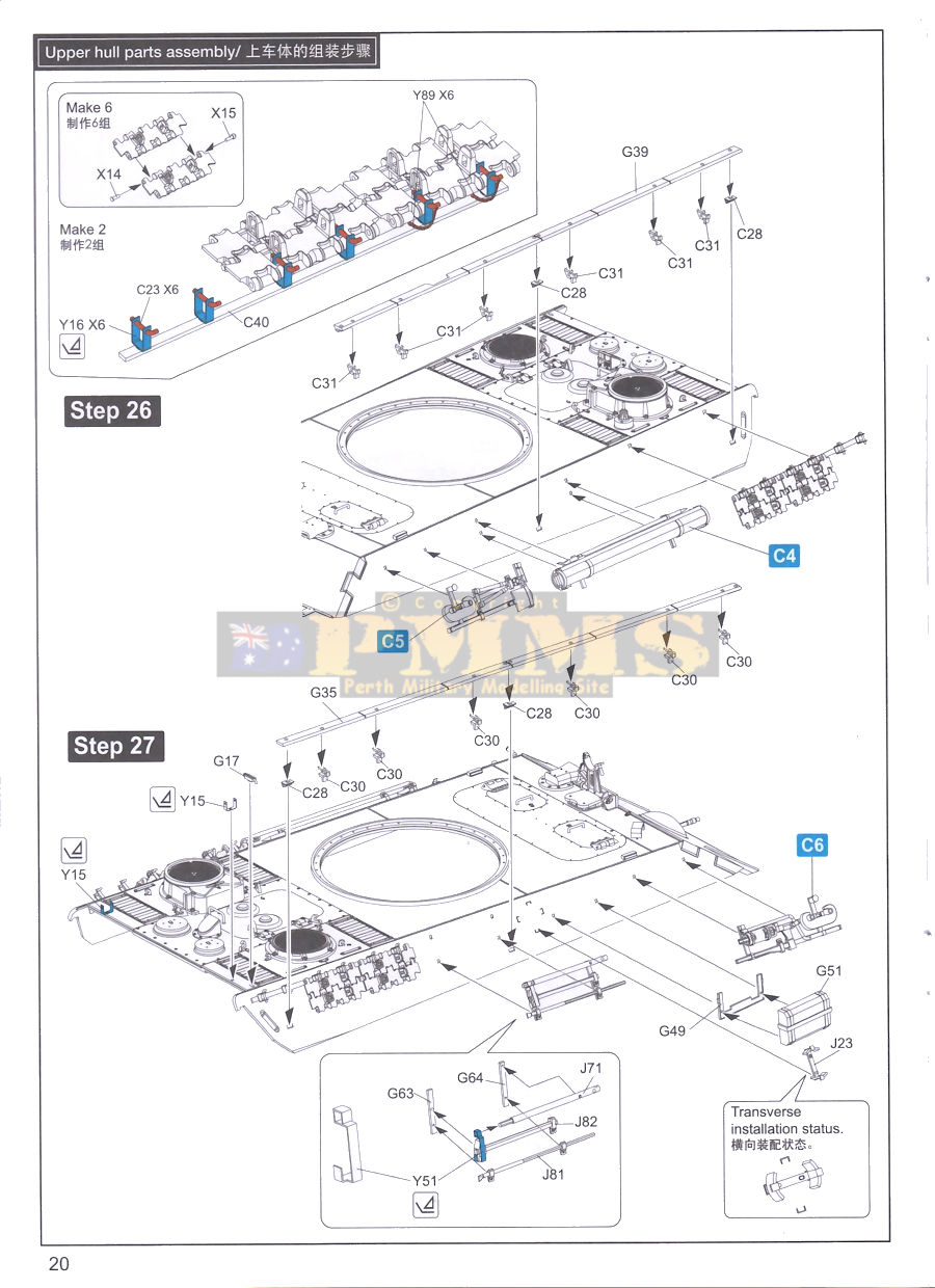
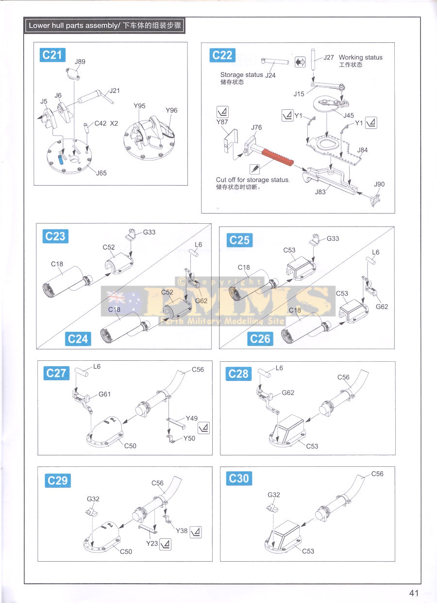
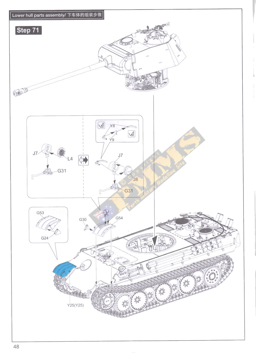
The remaining items added around the hull are the tool racks, barrel cleaning rod container, the spare track rack on the rear sides with PE track mounting brackets and the side strips with the Schuerzen mounting brackets but note there are no Schuerzen plates included with the kit.
The tools are nicely moulded with mostly the clips and brackets moulded with the tools supplemented with small PE brackets. As mentioned the twelve U brackets to hold the spare track links to the side bar are PE (Y16) with thin plastic pins (C23).
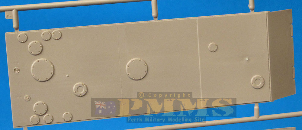
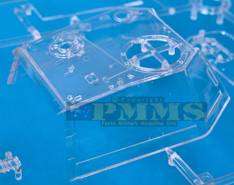
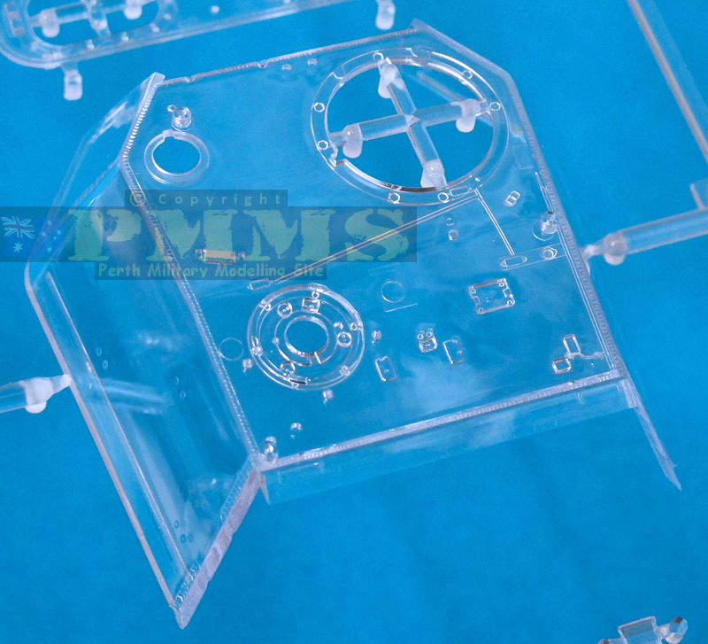
The turret shell and rear plate are in clear plastic with all other parts in beige plastic and as with the hull the only external surface detail is the armour plate welds and a few details include on the inside of the roof. There are four small pin marks inside the turret shell but three of these are hidden by other details fitted leaving just the one small mark to deal with.
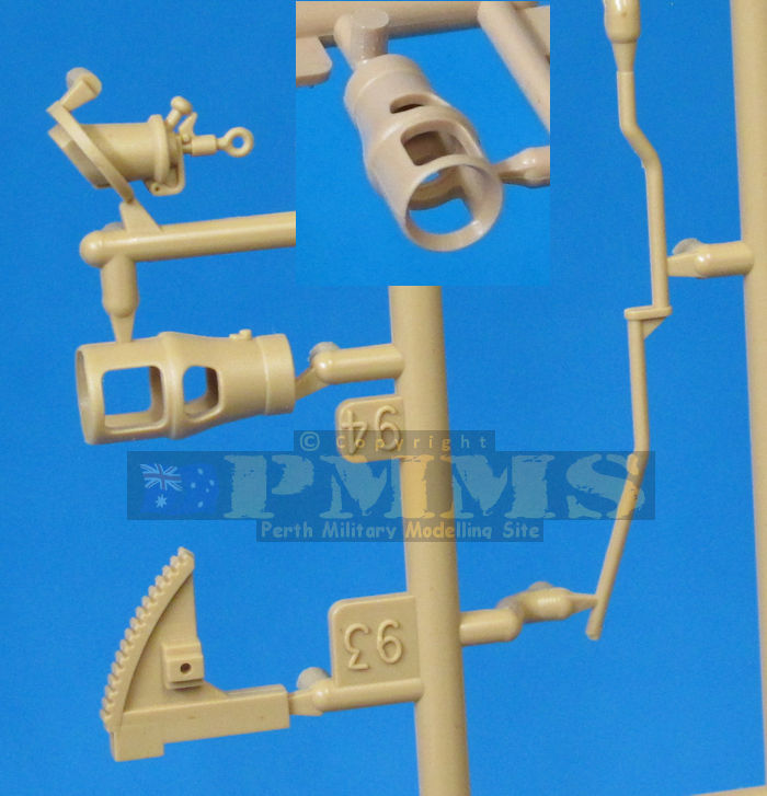
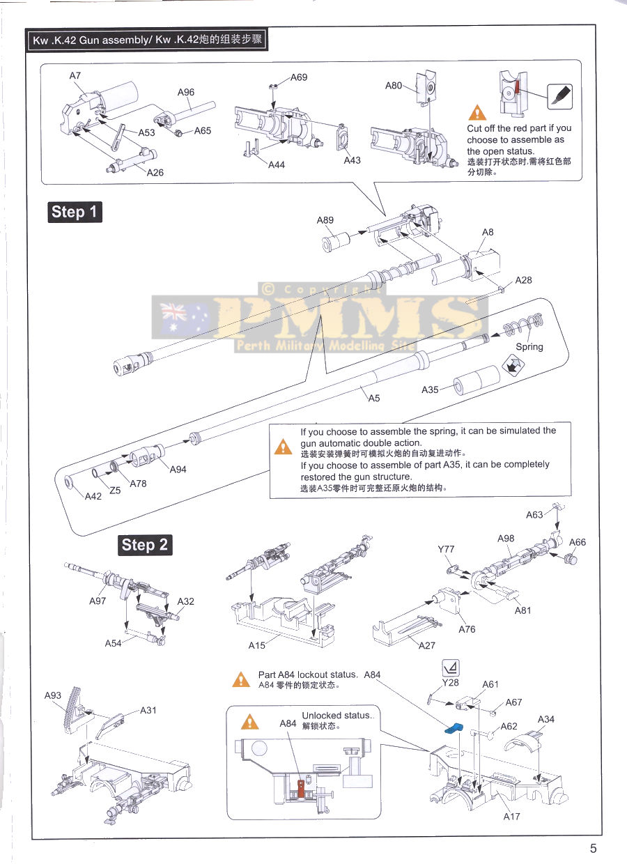
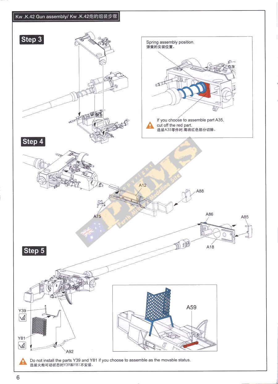
The 75mm barrel tube is moulded in one piece with just a fine mould line to be sanded along with a one piece slide moulded muzzle brake with two inner rings (one plastic, one PE) plus the separate end cap, this fits into a two-part gun breech with separate breech block and seven other detail parts. A large metal spring is supplied that allows the barrel/breech to recoil if you push on the muzzle as well as a solid plastic collar (A35) to use instead of the spring if you don't plan on playing with the gun after assembly. If not using the spring there are two supports moulded inside the main inner gun mounting halves (A15, A17) that need to be cut off before assembly.
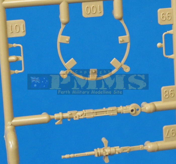
The remainder of the gun mounting is well detailed with the full co-ax M.G.34, sighting telescope, elevation quadrant and large breech guard on the left-hand side. There is also a large perforated PE shell guard added under the breech along with smaller details. Note; if you choose the barrel recoil this PE guard can't be fitted as it will foul as it recoils, another good reason to go for the static barrel assembly.
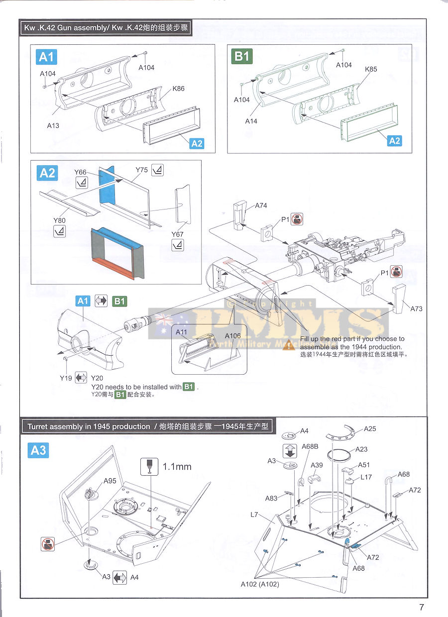
Alternate mantlets are included, the early curved (A14) and later chin mantlet (A13) with corresponding inside filler plates (K85, K86) plus a four-part PE 'box' that will need careful bending of the top/bottom and side parts as well as careful assembly with either cyanoacrylate or soldering. There are also alternate small PE rain guards (Y19, Y20) fitted over the outer sight hole for the appropriate mantlet used.
The side gun mountings to the turret front plate are two large plastic parts (A73, A74) that trap vinyl brackets that fit over the gun trunnions and held in place as you glue the side gun mountings to the inside of the front plate. The chosen mantlet is then slipped over the barrel and attached to the front of the main gun mounting assembly to finish the gun sub-assembly.
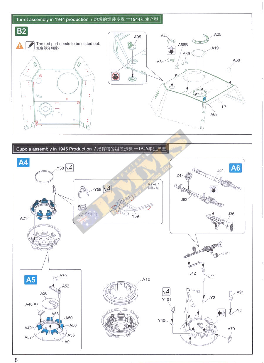
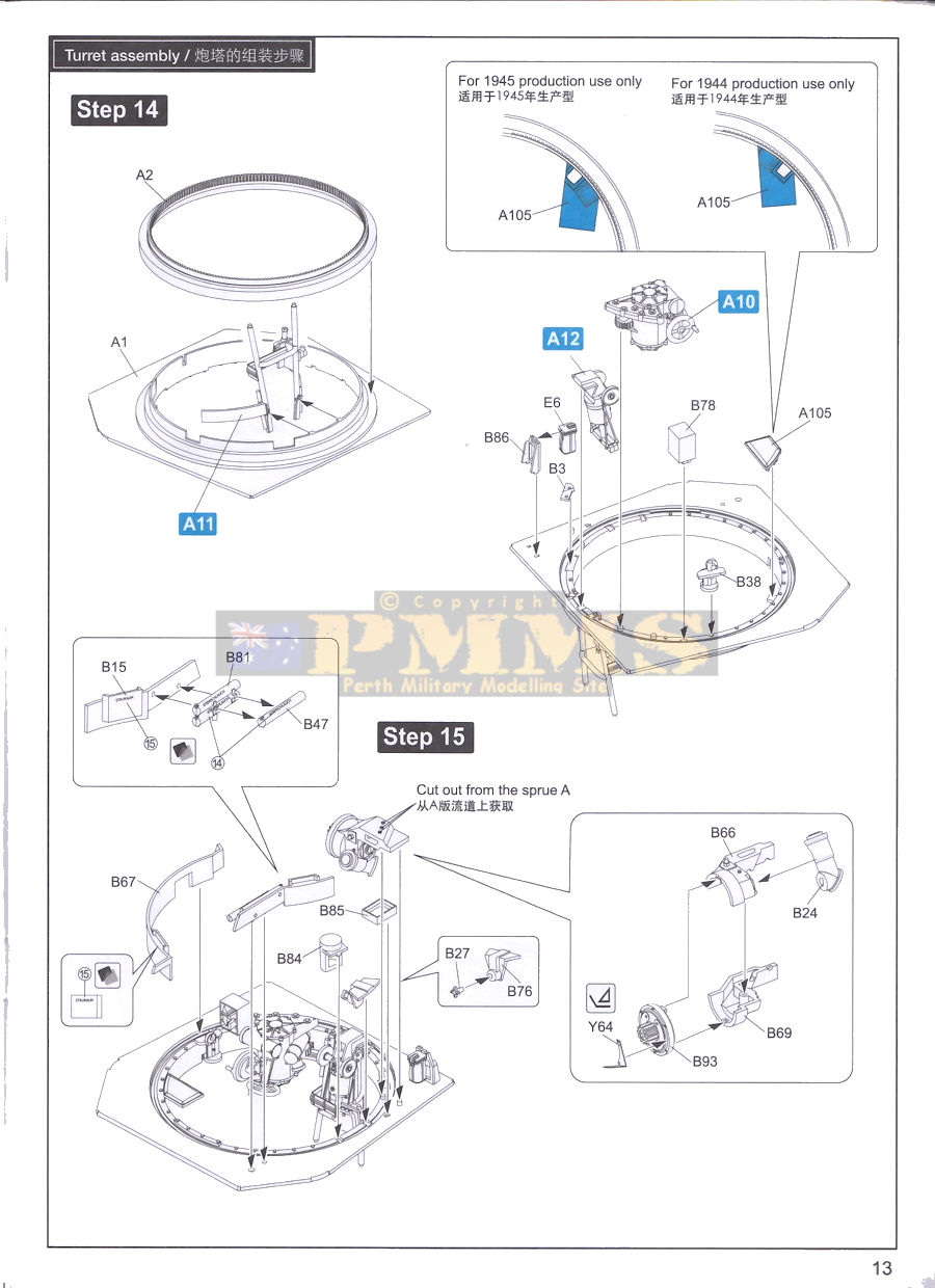
The clear turret shell as it comes is set up for the 1945 production with a number of locating points for items such as the five side handles and the extra roof details found on the later turrets, this means if you are building the earlier 1944 production turret these locating points have to be trimmed off before you begin assembly. On normal plastic this is no problem but with the clear plastic to stay clear you will need to carefully cut and sand these points and re-polish the plastic back to a clear finish. There is a diagram in the instructions clearly showing the small locator tabs that need to be removed.
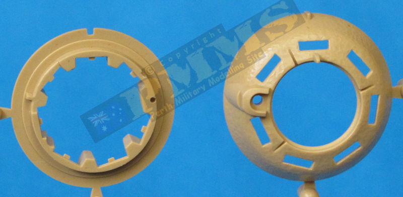
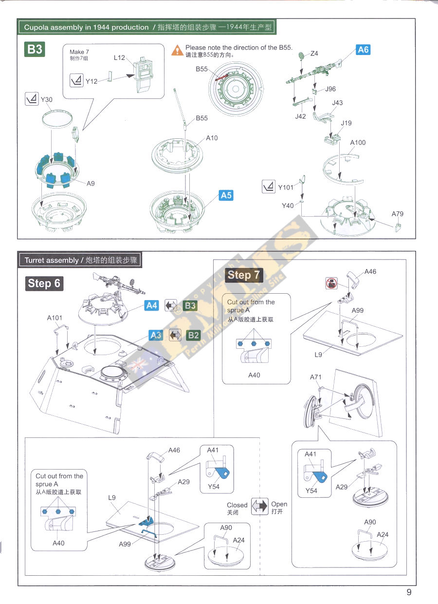
The Commander's cupola again has alternate parts for the early and late versions, the cast cupola dome has separate periscope guards and three-part hatch (post with grab handle and cover) with the periscopes in clear plastic with alternate inner support ring for early or late plus alternate MG pintle/mount with the nicely moulded M.G.34 with PE front sight, the instructions have clear illustrations on what parts to use for your chosen version.
The rear hatch has nice details inside and out with a multi-part latch that allows the hatch to be open or closed as you wish. There are a number of other parts added to the outside on the turret such as the top ventilator, grab handles and guards and as mentioned before you need to take extra care when gluing these parts to the clear turret shell to avoid excessive glue marks.
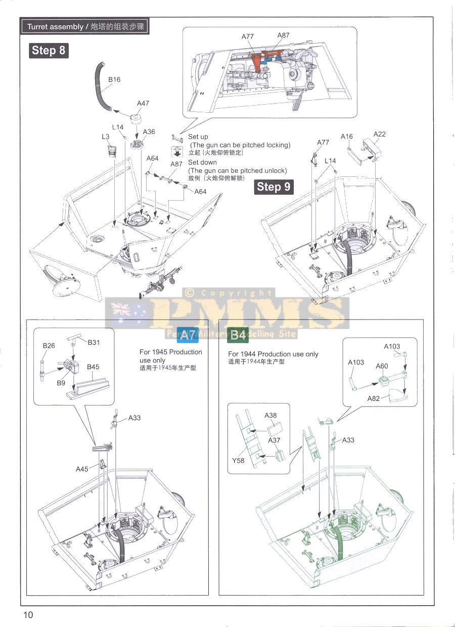
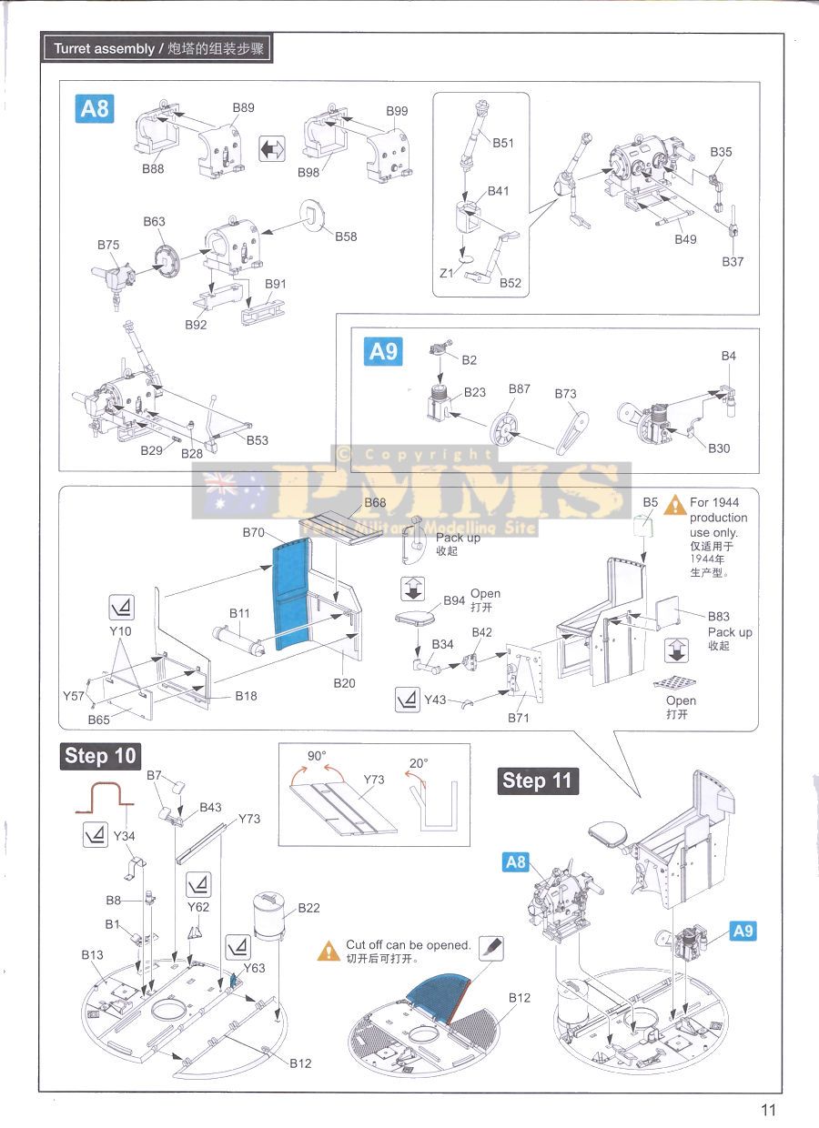
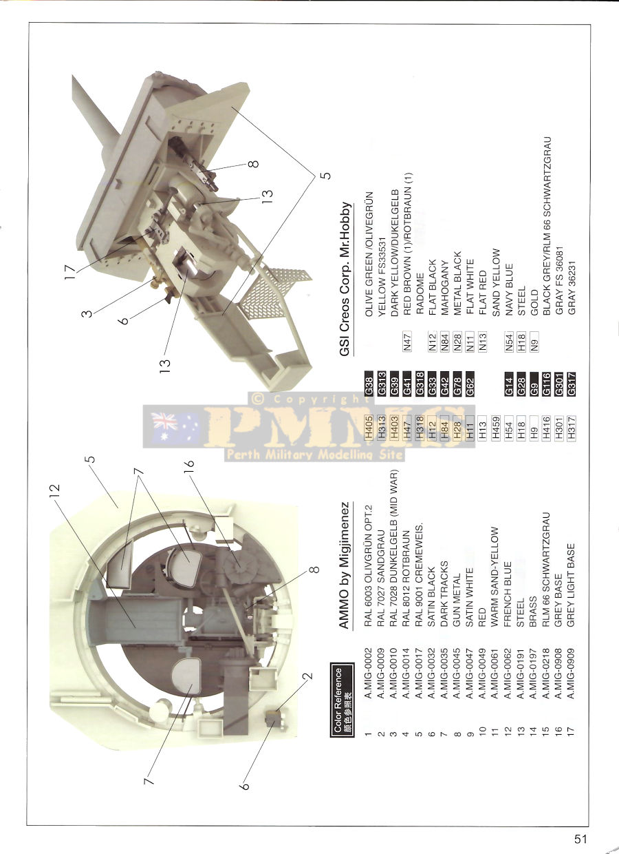
The turret interior also has alternate parts for the 1944 or 45 production models as noted in the instructions and has some quite intricate sub-assemblies, there are also small items glued to the underside of the roof and again take with the glue on the clear plastic.
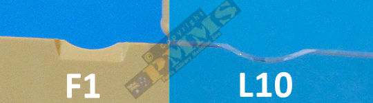
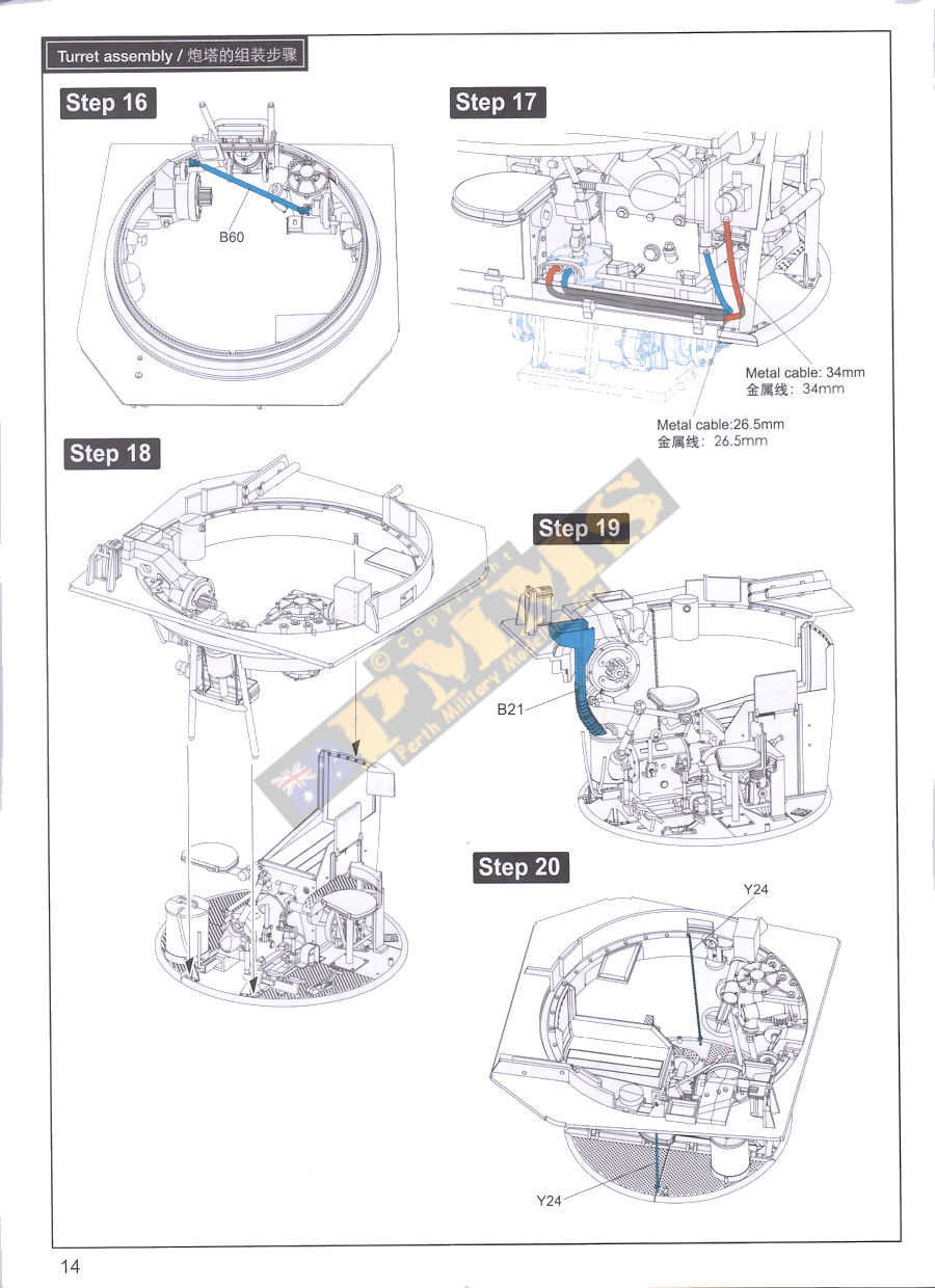
The circular turret 'basket' floor is in two sections with treadplate pattern as well items such as the traverse motor and axillary hand wheels, compressor, spent shell container and ventilator ducting tube, crew seats plus additional gear attached to the turret ring. This is supplemented with larger cables made from the metal cable supplied, the instructions have plan drawings of the larger cable with measurements to make bending the cable easier, others are shown in colour in the illustrations to show the exact location.
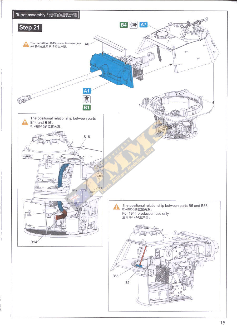
The final mating of the turret ring to the upper turret and gun completes a very 'busy' sub-assembly with much of this visible through the clear turret walls and roof in this kit.
Note; if you are building the kit to represent an early G produced between March and 9 September 1944 the hull and turret will need Zimmerit coating applied, there are various ways of doing this, so choosing your preferred method would be the best option.
The kit isn't for the inexperienced modeller and isn't a weekend job but making yourself familiar with the instructions and parts before assembly will help alleviate any major issues.
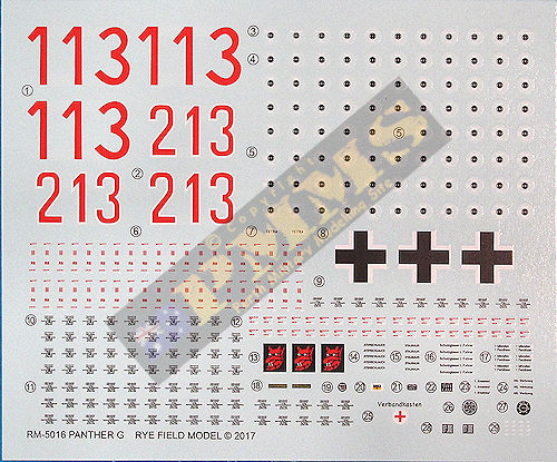
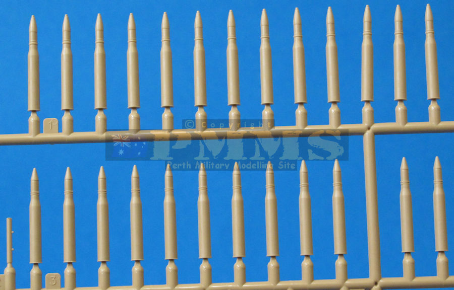
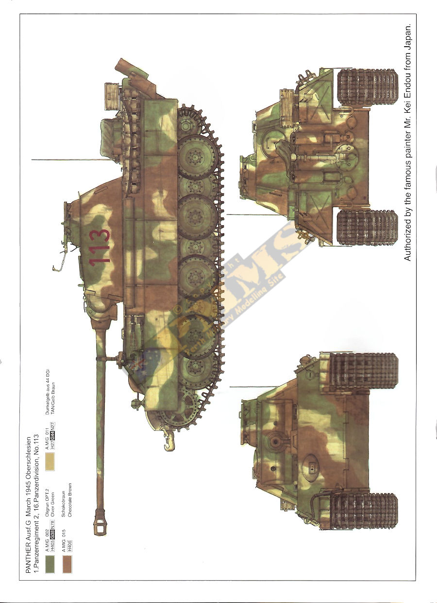
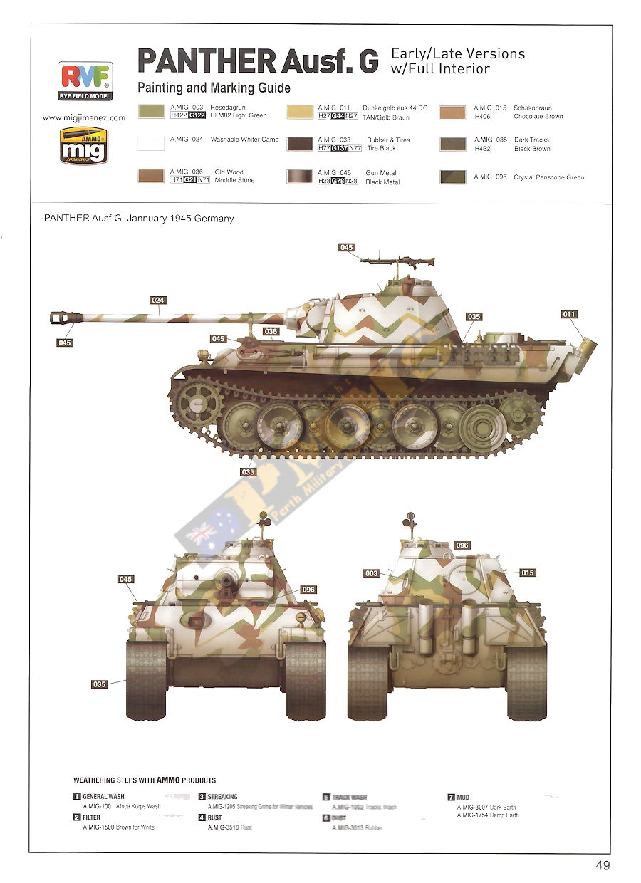
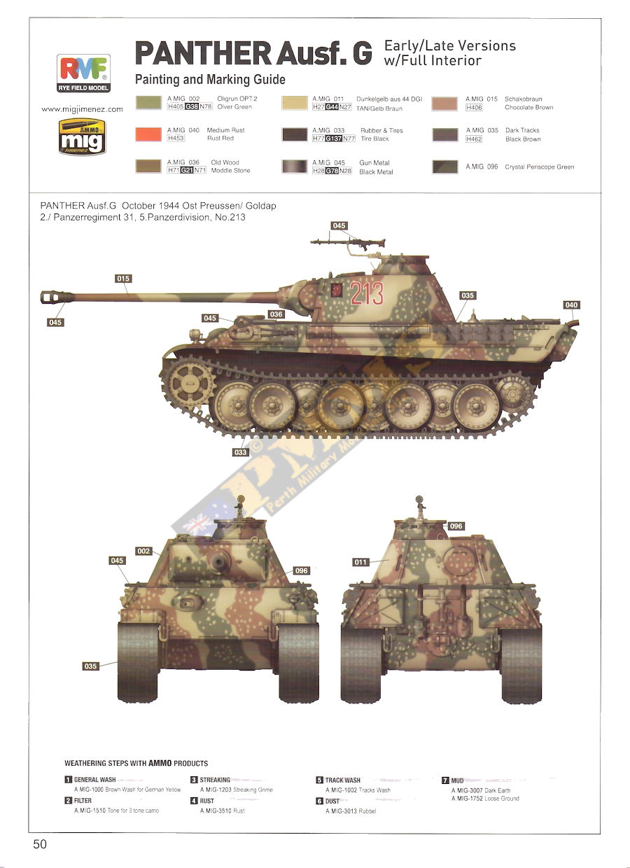
The colour painting guide lists paint colours from AMMO by Mig and Mr.Hobby and the decal sheet is nicely printed with good colour register and includes the markings for the three vehicle options as well as a good selection of stencil data for the three types of tank rounds included plus the driver's instrument dials and other internal equipment so watch out for the decal icon in the assembly steps.
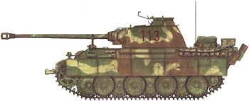
Option 1: No. 113 Oberschlesien 1.Panzer Regiment 2, 16.Panzer Division, March 1945
Option 2: Unknown Unit, Germany, January 1945
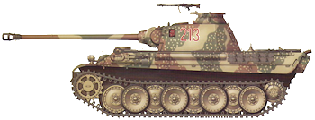
Option 3: No.213 Ost Preussen/Goldap 2./Panzer Regiment 31, 5.Panzer Division, October 1944
The kit is marked 'Limited Edition' so was can assume a similar kit will follow with normal plastic hull and turret parts included. While the detail included looks impressive there will be additions/corrections etc as there is with any kit but the starting point is most impressive.
First impression rating 9/10
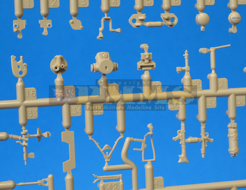
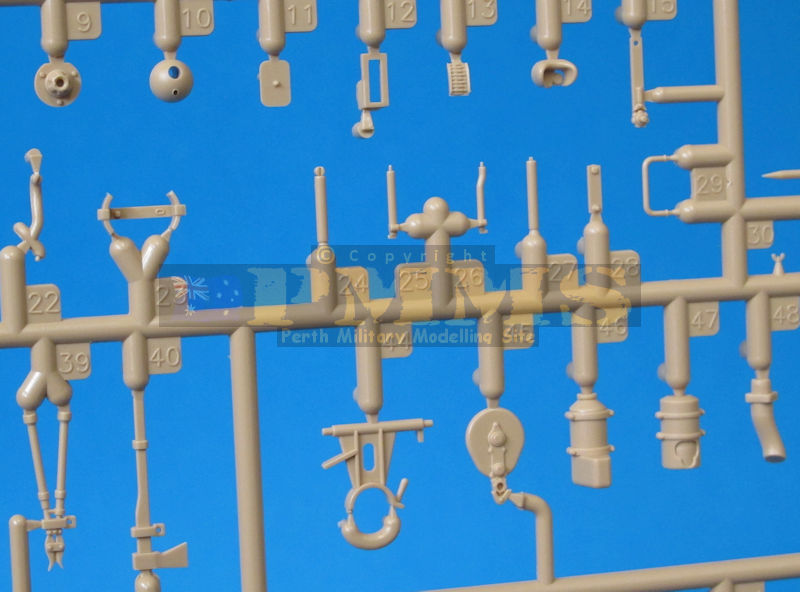
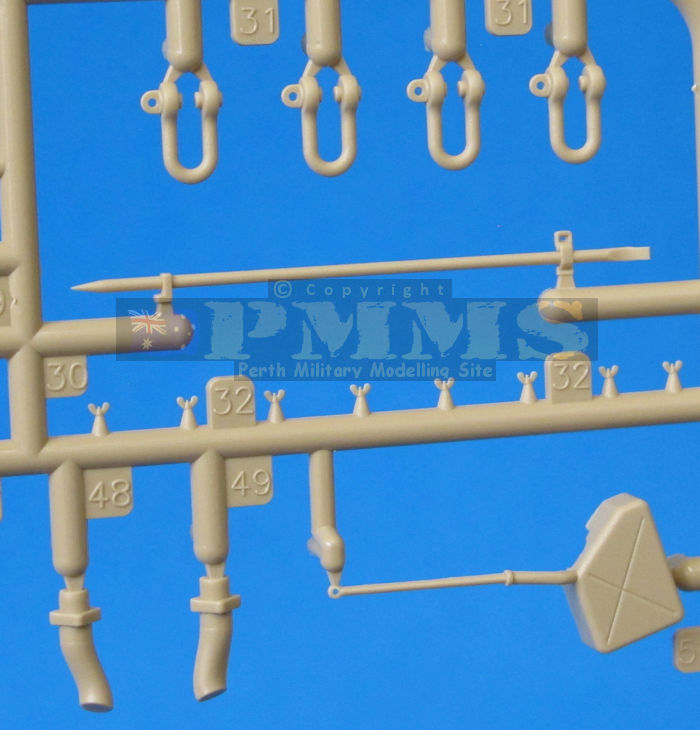
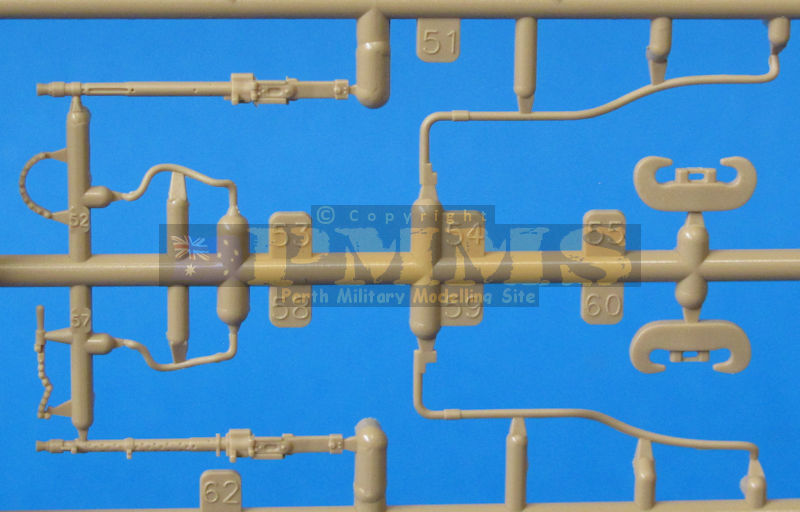
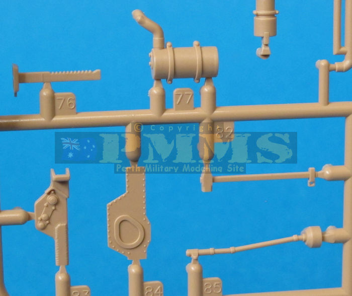
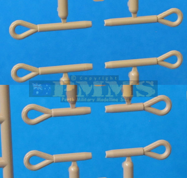
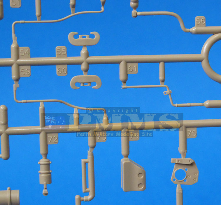
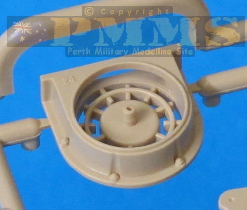
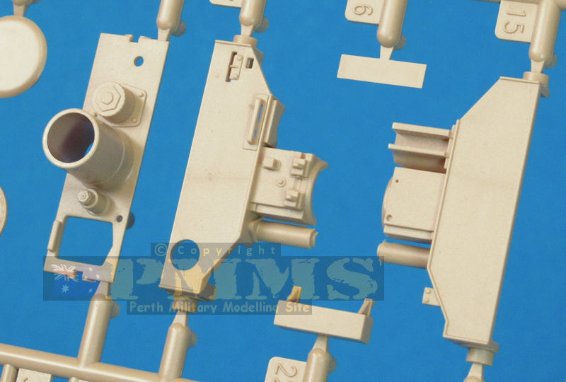
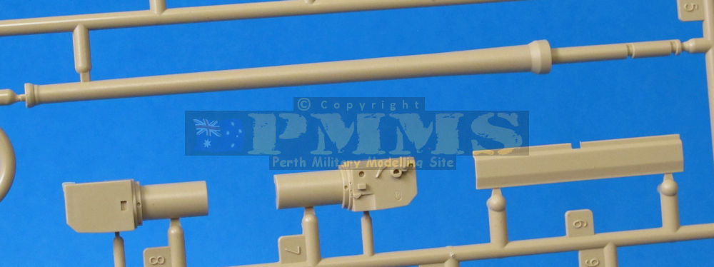
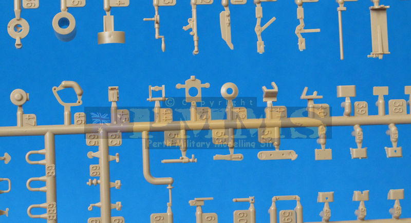
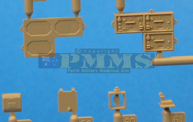
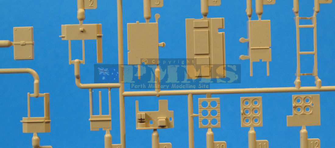
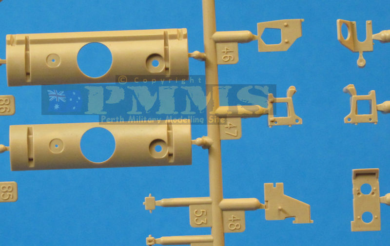
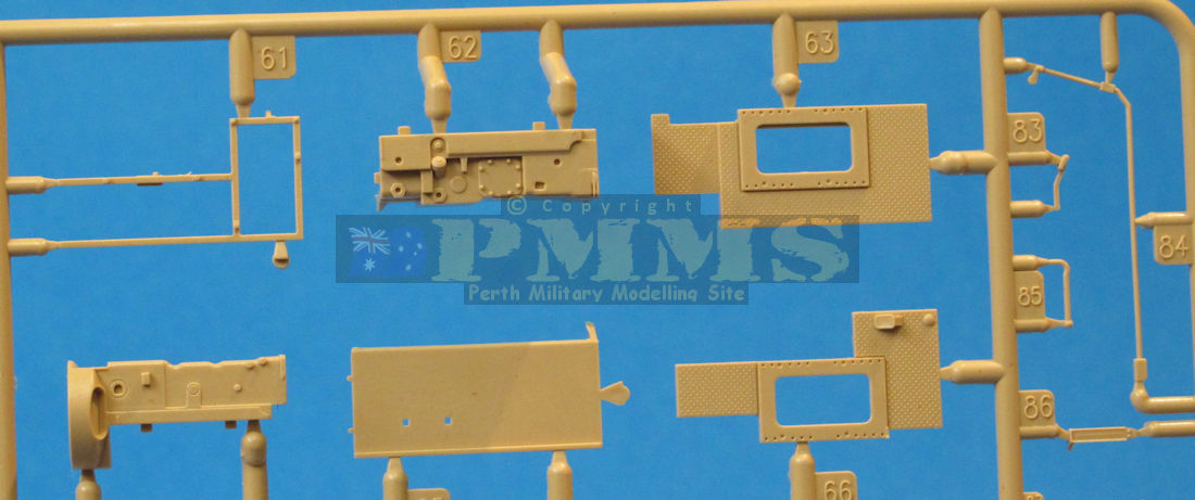
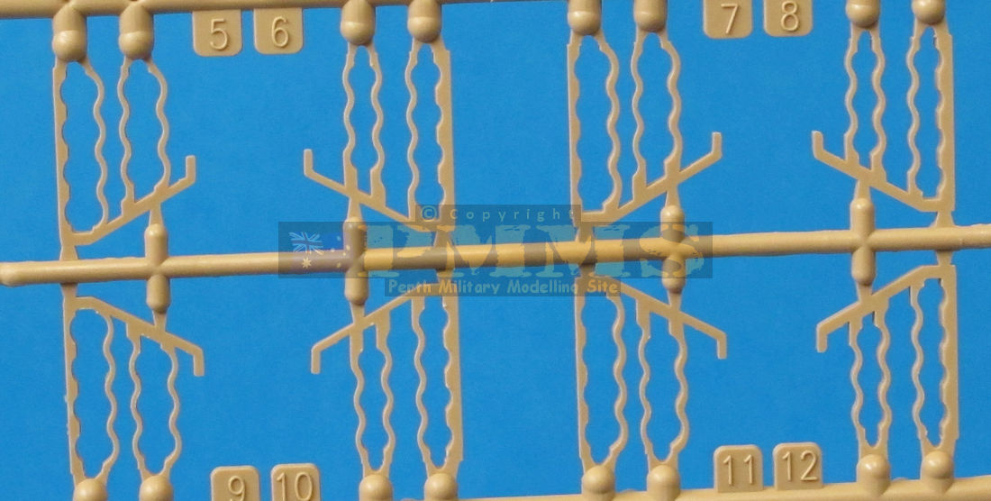
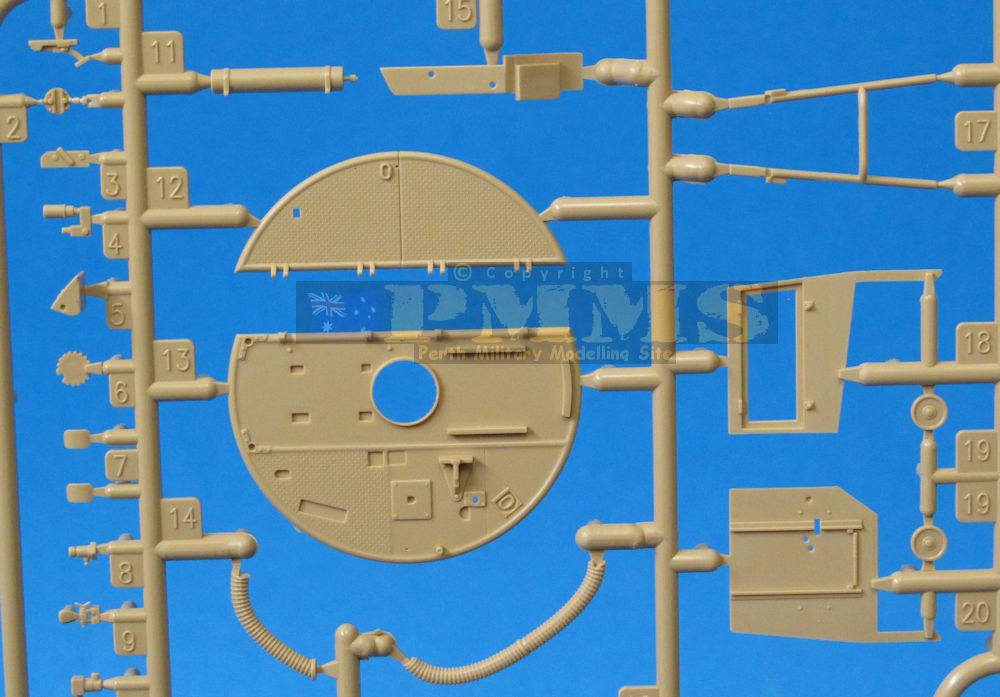
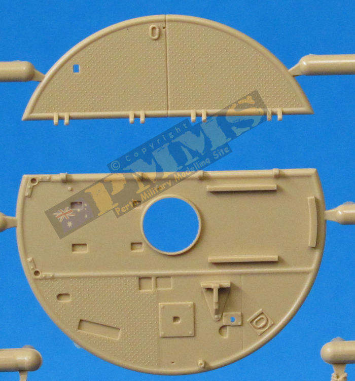
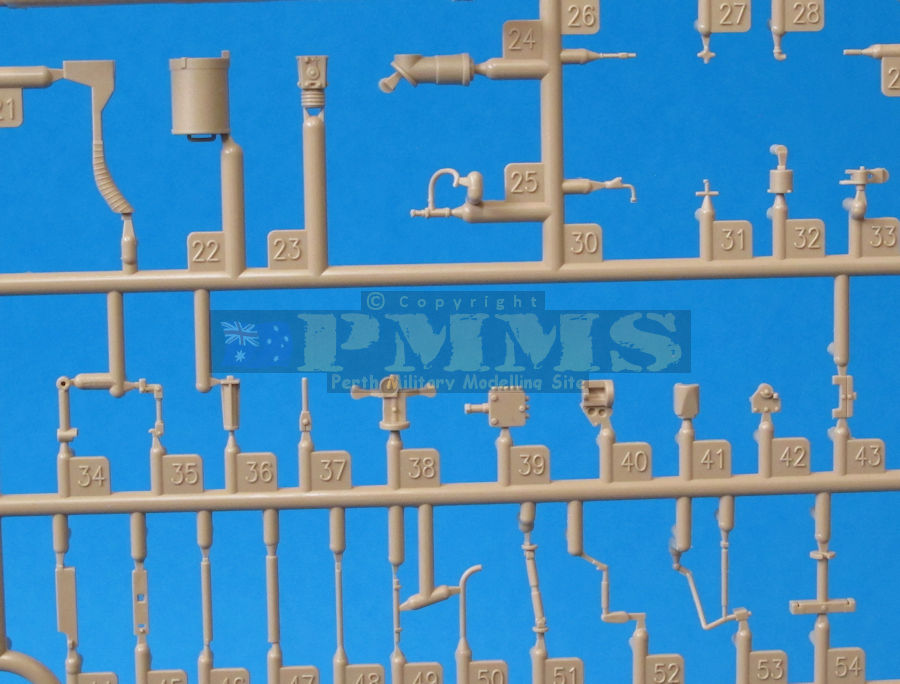
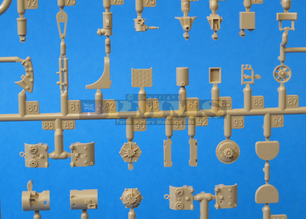
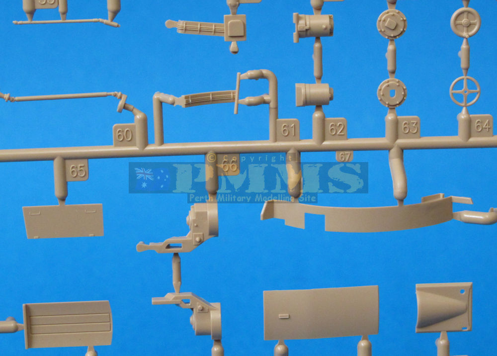
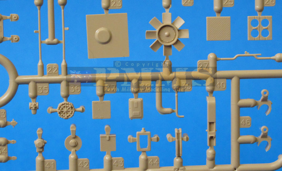
Kit Sprues
Click on thumbnails for larger view
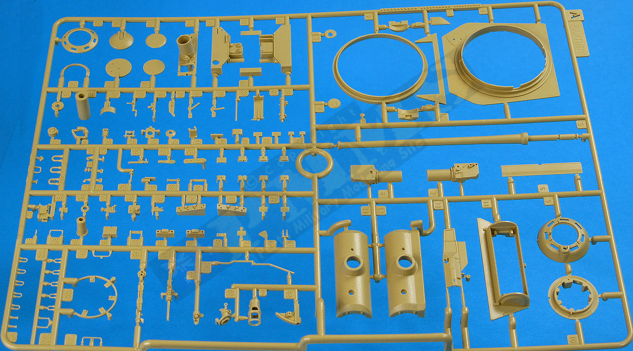

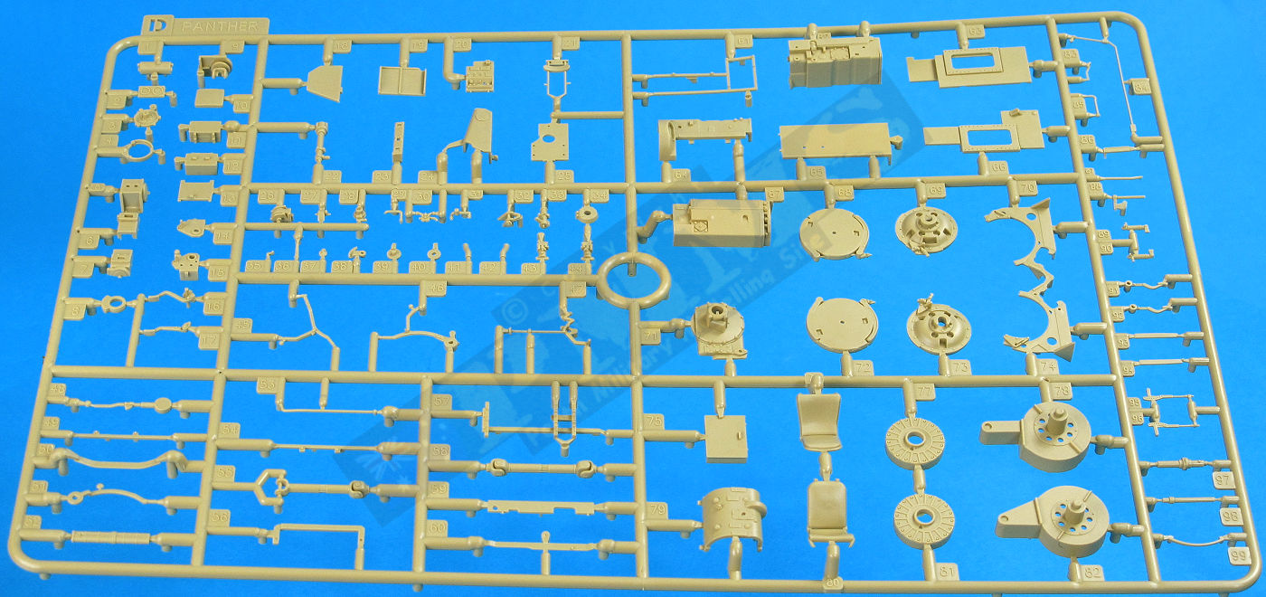


Sprue detail images


Instructions


Close new window to return to page
 |
Panzer Tracts No.5-3 Panzerkampfwagen "Panther" Ausfuehrung G by Thomas L Jentz and Hilary Louis Doyle ISBN 0-9744862-7-2 Published by Panzer Tracts, Soft cover, 68 pages. |
There is an almost endless list of additional Panther references, click HERE for a listing of some that are available.
Thanks to ![]() for the review kit.
for the review kit.
