

British Scammell Pioneer
TRMU30/TRCU30 Tank Transporter 30 ton
Thunder Model kit 35200
Rebuilding the Under-Cab Tray
Page 1 of 1
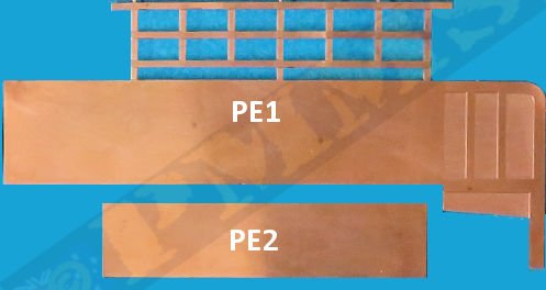
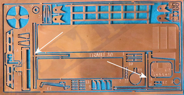
The contours of the PE forward end panel are not correct and as the PE is so thin the support arm rod that should go from the tray frame to the front edge of the cab is simply missing as there's nowhere to attach this to the thin PE panel. Other details not correct due to the PE is the location of the front bars, this is actually a fold down 'door' with the complete bar section able to open and fold down for loading and unloading the tray but the PE bars are attached directly to the floor and sides meaning it's fixed in place without any of the lower hinge or side latch details. The actual tray has brackets on the end frames to attach the top metal bar with pins holding this in place, resulting in the attachment point extending out from the edge of the end brackets.
The PE bars at the front are quite thin and as a result difficult to keep straight and there are some intricate bends on the main PE part (PE1) that will require careful bending with a good bending tool and you will need to solder the tray together to have any chance of it staying assembled. During the soldering parts of the tray were constantly bending out of shape due to the thinness and softness of the PE. The rear wall of the tray is a separate solid piece of metal (PE2) that just butt joins to the front section and needs to be soldered perfectly flush with the edges of the main tray and this requires some care in aligning the parts while soldering.
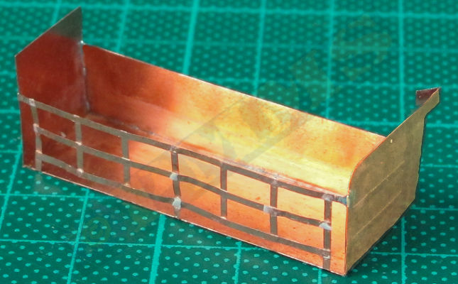
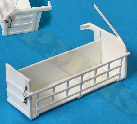
Assembled kit PE tray that lacks many details from the actual tray, see reference images below.
Reference images of the actual Under-Cab Tray. Note only image 4 is from an TRMU30 the others are from SV2S's which have different details on the
rear ends due to the different cab designs (e.g. image 5), other details are the same.
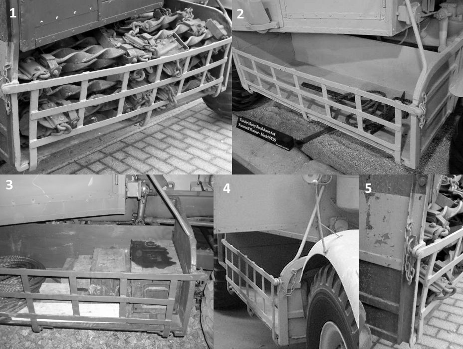
I don't know the copyright owners of these images, if your's please contact me and I'll add credits accordingly, thank you
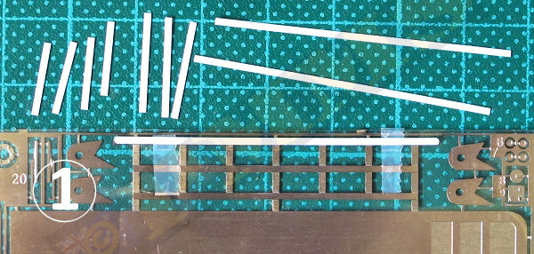
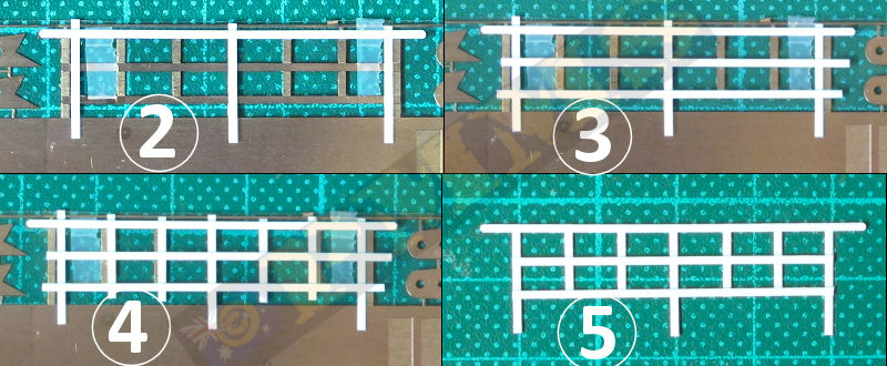
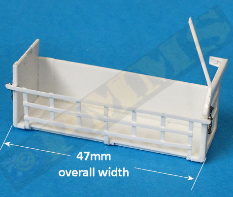
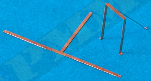
I used the kit PE rack as a template to form the new plastic strip bars, this is okay for the three horizontal and central vertical bars but the other vertical bars are spaced slightly narrower than the PE bars, this is due to the ends of PE tray being very thin but the end panels of the actual rack are about 1mm which reduces the spacing between the end panels to 45mm (instead of 47mm). Still using the PE tray template, you can just reposition the bars inwards slightly to get the correct spacing, See images for assembly sequences.
Update: I didn't have an image of the underside of the tray untill just now, so will have to modify the underside detail accordingly from that shown here.
sides. (1) Attach the top bar to kit PE "template" with Sellotape ensuring it aligns with the kit PE bar perfectly.
(2) Next fit the three vertical bars that extend down to the lower hinges when fitted to the tray body and secure with a dab of liquid cement.
I used the new Tamiya Quick Drying Extra Thin Cement for excellent results.
Note the outer bars are fitted inside the PE bars due to the reduced width as mentioned above, also note these bars fit 'behind' the Horizontal bars.
(3) The remaining two horizontal bars are fitted as shown, don't worry about the excess strip, this can be trimmed after final assembly.
(4) The inner four vertical bars are added (behind the horizontal bars) making sure the spacing is even between them (about 5.5mm each)
(5) With all the bars attached and firmly glued the assembled bars can be removed from the template and the excess strip trimmed ready for fitting to the tray body.
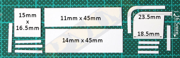
After completing the front bar grill the tray itself should be fairly straightforward as it's all flat panels and right-angle corners apart from the forward end panel top curve and the supporting rod bends. I firstly measured and cut each segment from plastic card and glued the two large tray body panels together as well as the end panels with the smaller sections of strip added for the details.
With the main sub-assemblies done the smaller details can be added, the two bar attachment brackets are spaced out from the end panels and not attached directly as on the kit PE parts, when fitting the brackets ensure they are aligned perfectly parallel for the bar grill to sit correctly. On the rear arm is the bracket to attach the forward tray to the chassis and this has two small triangular fillets and a large bolt head added while on the underside of the front tray lip are three hinges to which the bar grill 'legs' are attached and these are represented with small sections of thin plastic rod attached to a 1x1mm strip. (see images for the details)
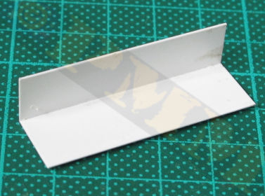
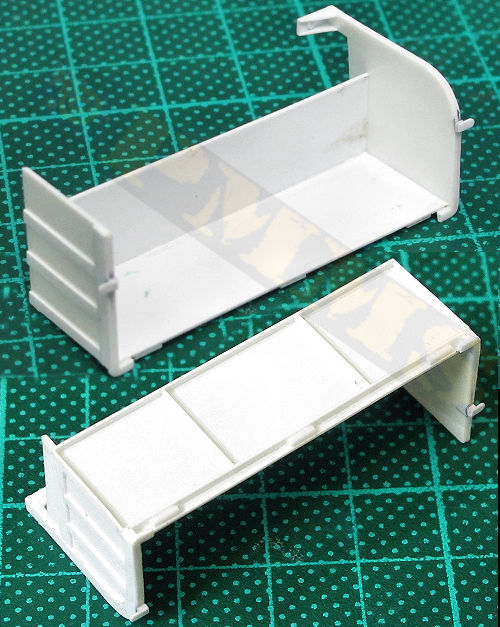
The main tray body floor and back are glued together at right angles. The join has the rear wall overlapping the back of the floor section.
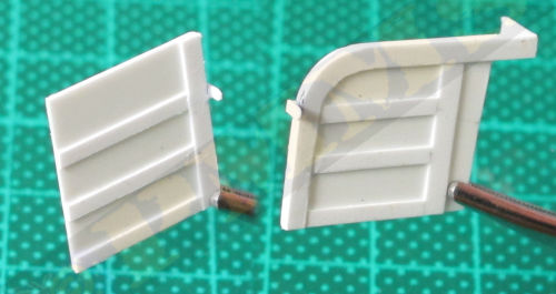
The assembled end panels with the separate strip sections glued in place, note the top curve of the front panel
compared to that of the PE part supplied and the two front attachment brackets for the bar grill door.
Also when fitting the bottom strip, glue this with half the strip overhanging the side panel to form the edges
of the underside bracing strip detail as shown in the underside two images below.
Close-up details showing the spacing of the front attachment brackets and the rear bracket with the two
small fillets and bolt head added.
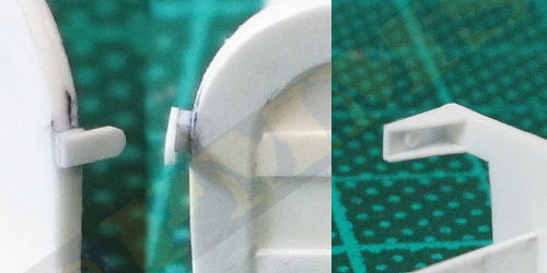
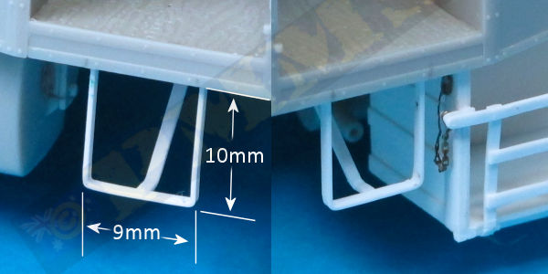
Final assembly of the tray body with the small curved extensions at the base of the side panels
and the underside hinge segments from plastic rod added. Note the bracing strips added to the undersides
from thin plastic strip.
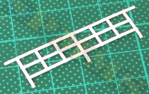
The assembled bar grill 'door', note the three extended bars are slightly bent at the bottom to blend into the lower tray hinges
when fitted to the tray body.
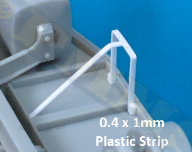
With the tray assembled and the from bar grill attached the support rod made from 0.8mm plastic rod can be added, this has a sharpish bend that needs care while bending to not snap the rod and lightly heating the rod will help with the bend. Do not heat this too much as all you will do is melt it, I just moved the rod close to a heated soldering iron tip momentarily and then bent the rod. The end section of the rod is flattened by trimming with a sharp blade and glued to the curved front tray panel, the upper end of the rod attaches to the front of the cab as shown in the images. Etched chains were used to simulate the chains holding the grill attachment pins to finish off the tray and you can attach this to the model or preferable leave off until after assembly is competed to avoid any damage along the way.
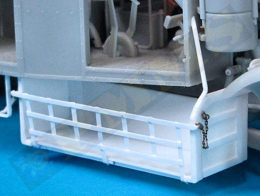
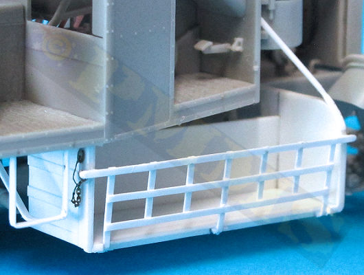
The re-built tray added to the underside of the cab in the same manner as kit PE tray, note the rear panel is located behind the underside cab rib.
Comparison of the re-built plastic tray with the kit PE tray which lacks any real detail at all unfortunately.
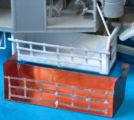
This gives a marked increase in tray detail over the kit PE tray and providing this in plastic may have been a better alternative to the PE but the PE is what we have.
PE rear cab steps bent to shape as per the engraved bend lines.
The plastic strip steps added to the cab, note the profile of the bends in the inner support bar as opposed to the kit PE parts.
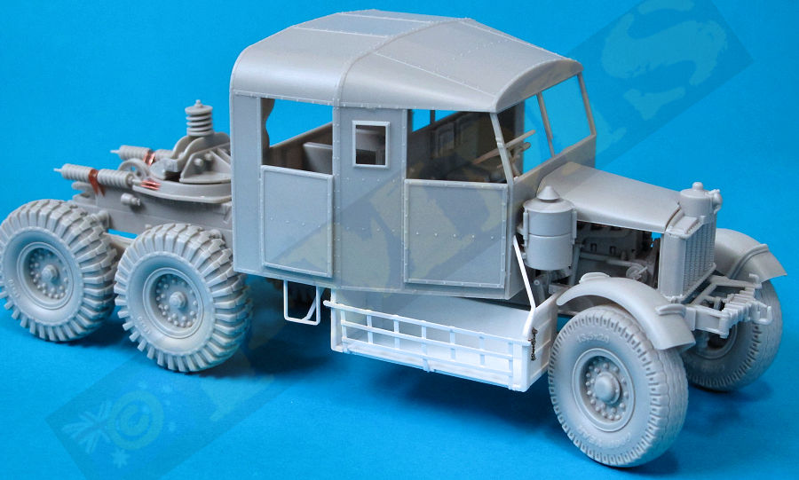
Overall view of the almost assembled tractor with the re-built under-cab tray and crew steps fitted as per above.
Hopefully this guide will of assistance in adding details to the kit tray and teps for those who wish to do so, this guide will be incorporated into the full kit review which will be posted shorty.
Note; the side 'back' and 'next' buttons are inactive but will be activated with the full review, thank you
| Scammell Pioneer SV2S, TRMU-30, R100 Army Wheels #AW18 Capricorn Publications  |
Pioneer: Scammell R100, SV1 and SV2, TRMU20 and TRMU30 in British Army Service Warehouse Military Vehicle Datafiles WD3 Warehouse Publications  |
| Scammell Maintenance Manual and Instruction Book Scammell Lorries Limited  |
The Military Scammell Illustrated Lizzie & Pat Ware Warehouse Publications  |
