

| Introduction: |
Following on from the kit review is this construction review built basically straight from the box to hopefully provide some tips during assembly.
The first thing to note is that there a many fine parts which make some assembly sequences rather fiddly and care is needed when removing the parts from the sprues as well as during assembly.
The gun is basically made up of three sub assemblies, the barrel and cradle, the carriage chasses and split trail arms. While the glue dries on one you can be working on another assembly then bring them all together at the final stage.
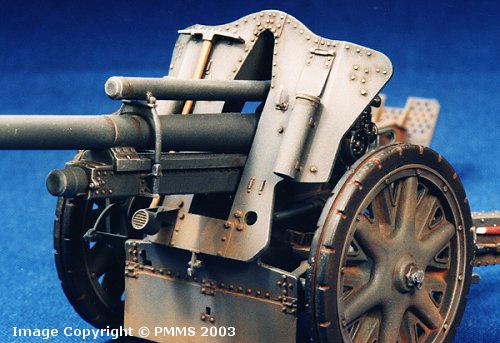
| Step 1 to 3; Barrel and Cradle assembly: |
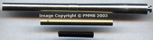
The two breech halves (parts A28/29) are a very tight fit around the end of the metal barrel but with firm finger pressure fitted well. The breech is made up of four parts and while this makes for excellent details there was some minor filling required on a couple of the joins. The breech block is another three parts and was a perfect fit through the assembled breech without modification.
The lower cradle has some small pin ejector marks on the inside faces that are difficult to remove, but aren’t very noticeable when the two halves are together.
The end cap (part A20) on the cradle helps align and keep the two halves firmly together, the centre join seam is all but impossible to remove from the inside of the cradle but the fit is good and this seam isn’t very noticeable. The seam on the outside requires some careful use of an Xacto blade to eliminate as there are many small bolt heads on the bottom of the cradle to negotiate around, but given the good fit of the two halves this wasn’t that difficult.
The crescent elevation racks (parts A3/4) fit well to the cradle with the elevation teeth trapped between them (part A5) take care that this part is aligned centrally between parts A3/4.
I glued the recuperator piston rod (part A11) to the breech attachment point at this stage; this made it easier when fitting the barrel assembly to the cradle. I also left the barrel assembly and cradle separate till later for ease of handling, the superb fit of the barrel slide to the cradle made this a breeze to take off and on and can be left unglued on the finished model.
I did vary from the instructions by adding the recuperator (metal part M1) and the recuperator support bracket (part A8) to the cradle assembly at this stage as I found it easier to line up correctly than later with the shield and other bits fitted.
One thing to note if you do this is that the support bracket (part A8) is
wider than the shield opening (which is why the instructions tell you to
attach the recuperator and bracket after the shield) but can be slipped
through the shield opening by first putting one side of the support bracket
through the shield opening at an angle and then with a slight twist
slip the other side through, but take it gently if you decide to use this
assembly sequence.
The two lower cradle halves (parts A32/33) fitted together trapping the upper
cradle between them without problems, except that the elevation wheel (part
A44) was a bit tricky to line up between the two cradle halves. I also glued
the front bracket (part A43) to the right hand cradle half (and let dry)
before joining the two cradle haves together, this made it a lot easier as
you don’t have to worry about lining this up as well as the elevation
wheel. The join seam on the lower rear of the cradle assembly has to be removed
after the glue has dried, that being the only cleanup needed on this assembly.
The air equalizer cylinder on the right side of the gun fits together well with only the minor join seams to be cleaned up prior to fitting to the cradle. The top and bottom caps on the cylinder help secure the two halves together and reduce the seam cleanup required. The dust cover (part R) for the air equalizer piston rod (part A6) has to be cut to the required length depending on the amount of elevation of the gun and it could be an idea to decide this now as it can’t be altered after assembly. For the elevation on my model I used 3mm of the cover, but you would use more for greater elevation; I also super glued the cover part to the cylinder before attaching to the gun support so it would be more secure when fitting the piston rod.
Finally the two elevation and rotation hand wheel assemblies are attached
as per instructions without problems (not yet anyway, more later), just make
sure that part (A49) on the left hand assembly remains movable between the
two attachment brackets (parts A45) as this will make lining up with the
lower chassis much easier later.
| Step 4 and 5; Shield and final cradle assembly: |
The accessories added to the shield are self explanatory and fitted without
problems, the only alteration was to thin the edges of the upper recuperator
shield on the inside of the main shield for a better scale appearance.
Just watch the inclusion of the tail light (part A38) for the vehicle towed
version only.
The shield fits easily to the gun cradle with the two lower and upper brackets
(parts A50/51) providing a secure attachment.
The fitting of the main sight (which is very well detailed assembly of two parts for the main sight and another two alignment arms) to the left of the cradle was a bit tricky. The instructions show the centre alignment arm (part D7) and sight should not be glued to the inner arm (part D8) as the sight should remain stationary while the inner arm moves with the cradle when the gun is elevated.
This results in the only attachment for the sight being
a butt join on the lower cradle wall and I felt this was not secure enough,
this
along with the fact I wasn’t going to play with the gun elevation after
assembly I glued the whole sight assembly firmly together with the sight
in the vertical position.
| Step 6 and 7; Lower Chassis assembly: |
This is a very detailed assembly with many small parts in a small space with the upper and lower chassis (parts B10/12) requiring some minor trimming to get a good fit but providing you take your time and follow the instructions there shouldn’t be any other problems. Alternate parts are provided for the horse or vehicle towed versions, these being clearly shown in the instructions for you to make the choice.
| Step 8 to 12; Split Trail Arm assembly: |
There are many accessories to be added to the trail arms and providing you follow the instructions noting the different numbered parts for the left and right arm there shouldn’t be any problems. One thing to note is that parts C8 and C9 are numbered incorrectly, part C8 should be on the right arm and part C9 on the left arm not the other way around as shown in the instructions. There are some alternate parts depending on the gun being in the firing or towed configuration which again can be used as per your choice.
All parts were glued to the arms before painting except the two sighting poles (parts B1 and B3) which will require some nifty masking when painting the red and white. The instructions have one to one scale diagrams of the poles to help get the red and white segments the correct sizes when applying the masks and paint.
The two large spades are different on each arm so watch the part numbers
for each and there shouldn’t be any problems.
If you choose to show the spades in the firing position some modifications are required on the arms and spades. A small bracket has to be cut off each arm and the frame on the spades has the squared up on the section that fits over the brackets on the arms, these alterations are shown clearly in the instructions.
Another thing to watch for is the thin grab handles moulded onto the outside edge of each spade. While these are moulded nice and thin they are very vulnerable to damage while both assembling the spades and attaching to the arms (trust me as these broke off a couple of times during assembly), so take care with these but they are easily re-attached if they should be broken off.
| Step 13; Attaching the trail arms to the chassis: |
Attaching the trail arms to the chassis is fairly straightforward but there are a couple of things you can do to make it easier.
There are two end brackets for each arm that attach above and below the chassis, watch the numbers and directions on these to get them the right way around but the instructions are clear on this so there shouldn’t be any problems.
I glued the upper brackets (parts B48/49) to the corresponding arms and let dry completely before attaching the arms leaving only the lower brackets to fit in place to attach the arms, this made the process a lot easier.
The cross arm support (part B4) has to be altered depending on your choice
of firing or towed position of the trail arms again clearly shown in the
instructions.
| Step 14 and 15; Final Assembly: |
The main wheels have the inside rubber section as a separate part for good definition and has a small fitting added to the centre hubs (parts B36), theses parts had a small sink mark in the middle and I added a thin hexagonal piece of card (made using a punch and die set) to cover this, you could of course simply use some filler to remedy this.
I left the wheels off completely until after the painting and weathering was finished to make this process easier, the exposed wheel attachments also gave a good place to hold the model during painting.
Fitting of the upper gun/cradle assembly to the lower
chassis is by slipping the cradle assembly over a small pin on the chassis
and attaching a bracket
(part A36) on the underside to secure which allows the gun to move. I
choose to glue the gun/cradle assembly firmly to the lower chassis for a more
solid assembly, but this is again up to you.
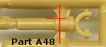 A
few problems arose with this assembly, the left elevation wheel support
bracket that fits into the left hand arm attachment (part A48) had to
be trimmed so it would sit a little lower in the arm to get the elevation
wheel support to align correctly.
A
few problems arose with this assembly, the left elevation wheel support
bracket that fits into the left hand arm attachment (part A48) had to
be trimmed so it would sit a little lower in the arm to get the elevation
wheel support to align correctly.
This entailed extending the narrower
section of the lower bracket pin (part A48) a little higher by reducing
The hand wheel on the right side of the gun fowled on the trail arm and
had to repositioned slightly higher on the cradle to get a clearance,
not sure if this is because the attachment of the hand wheel is in the
wrong
place or the arm attachment is slightly too high, but the alteration
fixed the problem. You may want to take this into account when fitting
the hand
wheel in step 3.
The lower part of the front shield is in two parts and the lower section
can again be positioned depending on your choice of firing or travel positions.
There are some pin ejector marks on the insides of these lower shield parts
but you can’t see these after assembly but if you show the lower
shield in the raised travel position you would need to remove the pin marks
from this part which shouldn’t be too difficult.
| Painting and Weathering: |
The model was given an overall coat of Humbrol Panzer Grey (#67) followed by a lighter over spray of the Grey (67) mixed with a lighter grey to get a lighter hue.
This was applied over the larger areas of the shield, barrel, wheels and trails to give a contrast to the final colour.
When dry the areas where the decals were to go were glossed using Xtracolor Gloss varnish and left to dry. The few small decals were applied using the Micro set/sol system and the decals adhered well to the model surfaces.
An overall coat of matt varnish was applied once the decals had dried and this was left for 48 hours to dry completely before weathering. During this time the detail painting such as the tools and sighting poles was completed.
The weathering was done by firstly applying a fine detail wash around the raised detail with a fine brush and thinned oil paint (a mixture of Burnt Umber and Black). This wash can also be used to ‘dirty’ up the lower parts of the gun carriage, and any excess wash is removed with another fine brush moistened with clean Humbrol thinner. When the wash had dried the model was drybrushed with a light grey colour to highlight the details add ‘wear’ in appropriate places.
Pastels were then used to add the earth colours on the wheels and around the lower sections of the gun and trails.
This completes the assembly and the kit that builds into a very nicely detailed model with only a few minor problems as above; the finesse of the plastic parts and the metal barrel and recuperator makes the gun look even better. There are a few parts not used on the sprues for this model, these are extra pioneer tools which are fitted to the carriage of the leFH18/40, could it be we will see this version also?
Return to Kit Review:
| The Sprues: |
Click on thumbnails
for larger view
Sprue Images
Detail Images
| References: |
 |
Leichte Feldhaubitze 18, GW II für le.F.H. 18/2 „Wespe“ and „Hummel-Wespe“ Nuts & Bolts Volume 33 by Joachim Baschin, Martin Block, Heinz Tippmann soft cover german & english texts 184 pages, 353 photos, (198 historic, 40 model, 115 modern), 40 blueprints, 13 camouflage schemes, tactical markings, table of organsisation (KStN) |
 |
Le.F.H. 18/18M Superb photo coverage of the le.FH.18/18M |
 |
WWII German and
Soviet Field Howitzers in detail Wings & Wheels Publications. Special Museum Line No25 ISBN 80-86416-24-0 Published by RAK, Czech Republic. 60 pages all in colour. It should be noted that this book features the leFH18/40 which is based on the 7.5cm Pak 40 carriage as well as having a muzzle break fitted and slightly different gun shield from the AFV Club kit. The gun and cradle are basically the same so can be used as a reference for those details. |
 |
Allied-Axis The Photo Journal of the Second World War No.7 Ampersand Publishing. The publishers of MMIR magazine. |
 |
Allied-Axis The Photo Journal of the Second World War No.8 Ampersand Publishing. The publishers of MMIR magazine. |
 |
German Light Field Artillery in World War
II Schiffer Military Books ISBN: 0887407609 Size: 8 1/4" x 11 3/4" b/w photographs, line drawings 48 pages |
Thanks to my credit card for the review kit.