
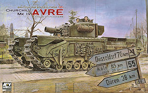
Churchill Mk.IV AVRE
AFV Club 1:35 Kit No. AF 35169
Review by Terry Ashley
The Churchill AVRE series of vehicles was the brainchild of Major General Sir Percy Hobart following the disastrous Dieppe (Operation Jubilee) raid in August 1942 which saw the Churchill tanks of the Canadian Calgary Regiment decimated on the beaches due to the lack of adequate engineer support.
The result of this and Hobart’s ingenuity was the creation of a series of specialised AVRE vehicles based on the Churchill Mk.III and Mk.IV chassis with the main gun replaced with a 290mm Petard spigot mortar affectionately know as the “flying dustbin” due to its appearance. The 40lb projectile contained a 26lb demolition charge with an effective range of 80 yards.
The hull BESA machine gun was retained but the co-driver’s hatch was replaced with a sliding hatch that allowed the Petard launcher to be “broken” and re-loaded from within the hull affording the loading the full armour protection during the reload.
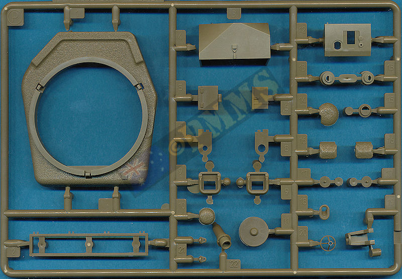
The kit includes the original flat panel air intake trunk panels and the low profile twin hatch Commander’s ring and the correct style periscopes from the previous Churchill kits and with all the appliqué panels being separate parts there is no problem building the kit in the configuration most commonly seen around the 6th June 1944 and after.
Also included are the standard AVRE hull mounting brackets for a large variety of specialised engineer equipment and the success of these vehicles was helped by the versatility of this design allowing different equipment to be fitted as well as other more specialised vehicles such as the ARK.
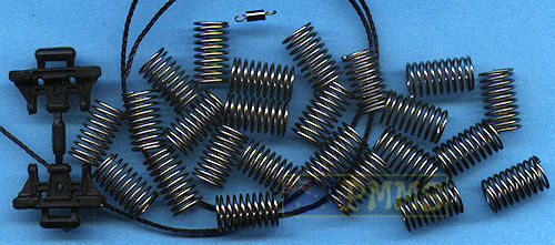
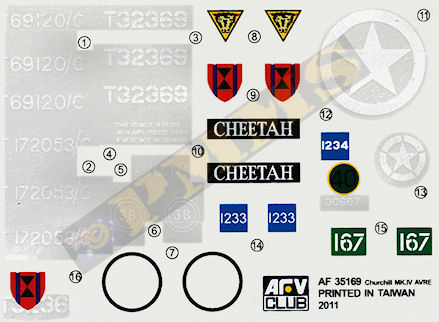
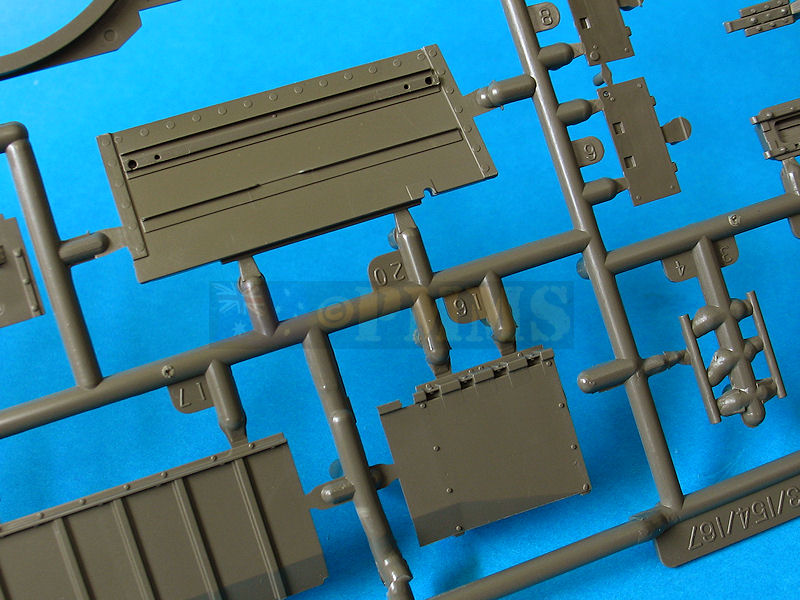
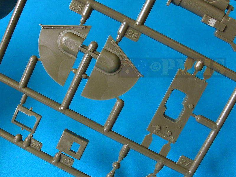
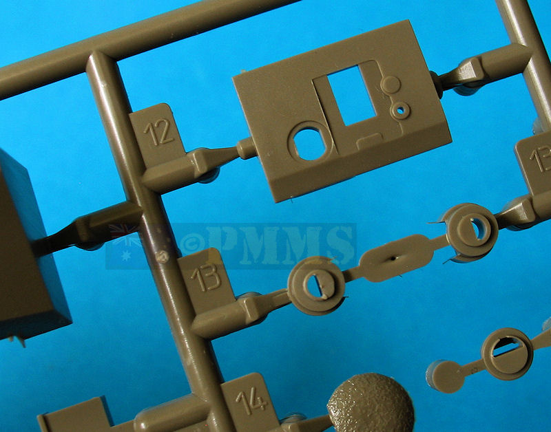
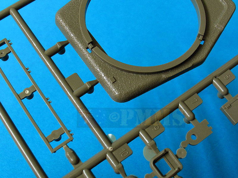
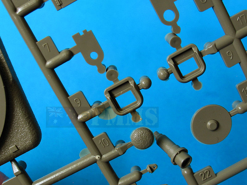
This mutli-media kit consist of 546 parts in the usual green plastic, a further 150 individual track link parts, 20 clear plastic parts, 41 etched parts, 25 steel springs, a length of thread, a couple of poly caps and the two full lengths of soft vinyl track. Added to this is the decal sheet, 20 page instruction sheet and the now standard poster with just the box art image of the Churchill MK.IV AVRE to add to the collection.
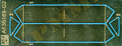
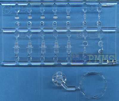
Metal and vinyl parts
Full lenght soft vinyl tracks
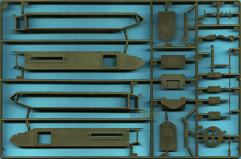
The standard of plastic moulding is very good overall with clean crisp details although there is a bit of fine flash on some of the smaller parts and those from the initial Churchill kits that have been around for a while now plus the odd shallow pin and sink mark but nothing to get excited over as these are easily cleaned up. Also some of the mating surfaces on the older parts needed smoothing out and checking this as well as test fitting all parts will reduce any issues along the way.
One thing to watch is there are many very small plastic parts and removing these from the sprues will need care as a couple were damaged in my kit due to the sprue attachment especially where there is a chunk of sprue between two small parts. You will need to take care with these as well as working well over you bench as dropping some of these on the floor could result in problems. The etched parts are also well done with fine bending lines to aid in the simple bending where required.
Dimensionally the kit measures up well against available data and the 1:35 plans in the recent GUNPower book and in older issues of Panzer and Tank magazines which have been reproduced in more recent Ground Power issues. The turret dimensions match well to resized ordnance drawings in "Mr.Churchill's Tank" with only some of the smaller items needing attention.
The kit is basically the previous Churchill Mk. IV (kit #AF35154) with the AVRE parts from the MK.III AVRE kit (#AF35167), the turret included is the initial cast Mk.IV layout with the ventilator located over on the left side of the roof, as such the earlier layout without the hull side appliqué armour would be the most appropriate version. Note the review kit has been built with the appliqué armour just as an exercise to show this configuration and isn’t indicative of the version that should be built.
As the Churchills underwent numerous upgrades with many newer features retro fitted to early tanks so these later features are quite feasible so I guess you have to decide on building the original early Mk.IV turret layout or probable upgrades undertaken.
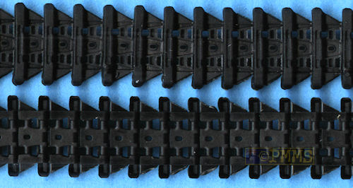
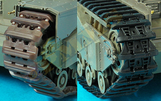
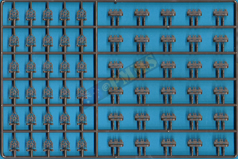
Also included in the kit is a choice of two sets of tracks, the previous full length vinyl T-144 Double Pin Manganese track and the individual link working B.T.S 3 Heavy track from set #AF35183 to use as desired.
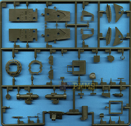
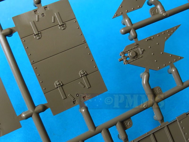
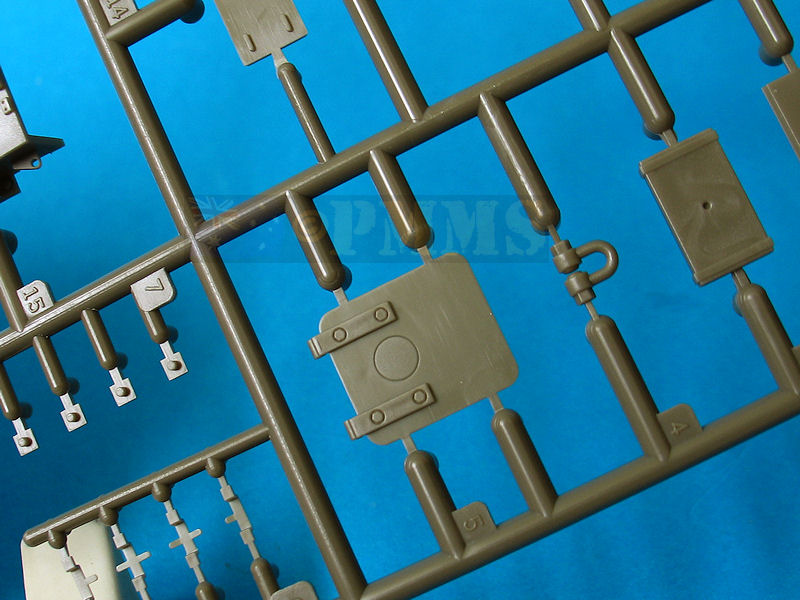
The side panniers are in two parts with the entry hatch opening and surrounding lip detail as well as the openings for the air intakes, you also have to drill out the holes for the large bolt heads and the appropriate AVRE type mountings and fittings. AFV Club for convenience identifies Type A as the version with the appliqué armour panels and Type B as the “standard” AVRE type so you should choose the version you will be building early on, note there are also alternate bolt heads to use with the choice of finish.
The instructions don’t mention the hole size to drill but you should use a 1.4mm (3/64th inch) drill for these and you also need to watch as the bolts are in different positions on either side of the hull with an extra hole location included on the right side (part C2) that shouldn’t be drilled out, so take care here.
Removing the very small bolt heads from the sprues will require care with the cleanup of the sprue attachment bur but fitting into the drilled holes in easy. AFV Club have also released a set of brass bolt heads (set #AG35020) if you want a little crisper definition on the bolt heads but this is only marginal with the biggest advantage of the brass bolts being no cleanup required.
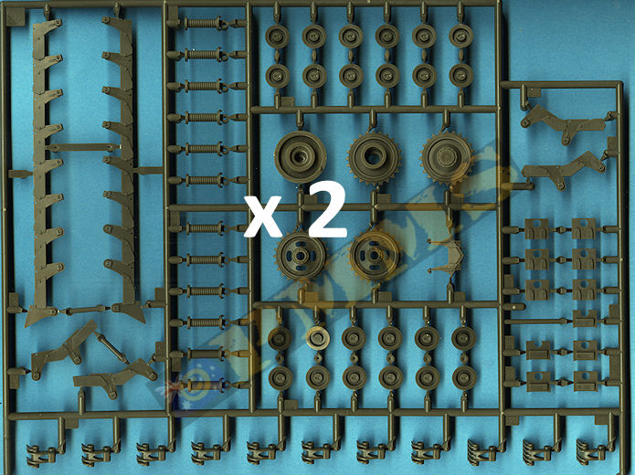
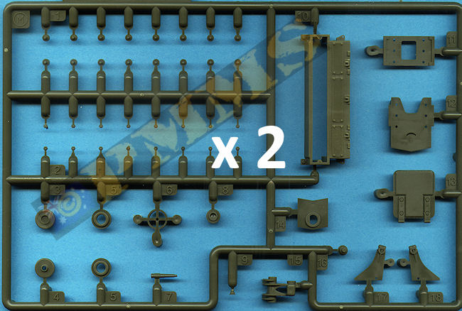
The suspension on the Churchill is quite a complicated affair and this is replicated on the kit with the fully workable suspension springs looking very much to scale when compared to photos of the real suspension.
The suspension itself is made up of about 50 parts per side and will need care and patience during assemble as quite a few parts shouldn’t be glued especially if you want the suspension to articulate after assembly and it also aids during assembly to leave the springs posts in particular unglued.
You firstly slip the metal springs over the suspension posts (parts D5, D6) and then sit the posts into the recesses in one side of the panniers, the springs will help keep these in place while you attach the other pannier half but don’t actually glue the suspension posts in place as leaving these free will aid in lining up the axles with the lower suspension arms later. Don’t worry about the large join seam between the two pannier parts as this will be hidden after assembly in any case.
The outer suspension mountings are in two parts each due to the front section being different on the Mk.III/IV and added between these mountings are 11 cross members, there are actually four different types of cross members numbered D17, D18, D19 and D20 so take careful note of the parts and their location. I actually numbered these with a fine felt pen before removing from the sprues top avoid any confusion, the same goes for the 11 axle mountings which are also different (parts D21, D22, D23).
After attaching the cross members to one side mounting and let dry you then slip the appropriate axle mountings in place and glue the cross members to the other side mounting ensuring you do not glue the actual axle mountings in the process. Adding 2 or 3 axle mountings and gluing as you go is easier as keeping all 11 axle mountings in place while fitting the side mountings is all but impossible.
Once the glue on the axle mounting assembly has dried this is then fitted over the panniers and spring posts and it best to do this initially with the axle mountings facing downwards so gravity will hold these in the down position allowing the posts to ease into place. If you try and fit this the other way the axle mountings get in the way of the posts causing a few hassles.
After fitting the axle mountings over the spring posts you then have to align the axle stubs on the posts and axle mounting and this is where leaving the posts unglued will help as they may be facing the wrong way initially.
You then fit the road wheels in place which secures the axle stubs but strangely the fit of the wheels was so tight on my kit the wheels do not rotate but the suspension springs articulate very nicely as the springs are strong enough to push the wheel back into position after being depressed if you want to articulate the suspension for a diorama or such.
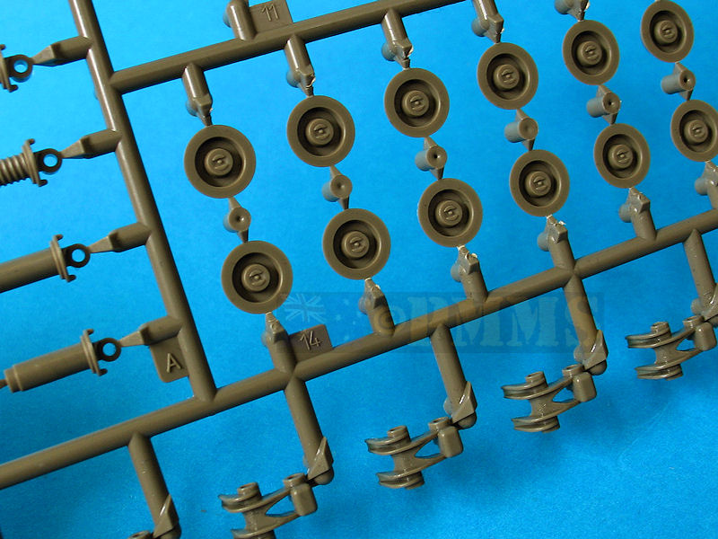
Just a quick note on removing the road wheels from the sprues as care is needed due to the thin edges of the road wheels so make sure you cut well away from the edge when removing the wheels from the sprue and trim later to ensure there is no damage the road wheel edges.
Detail on the road wheels and suspension parts is very well done and matches photos of the real things perfectly and the assembled suspension looks very much to scale even with the full articulation possible.
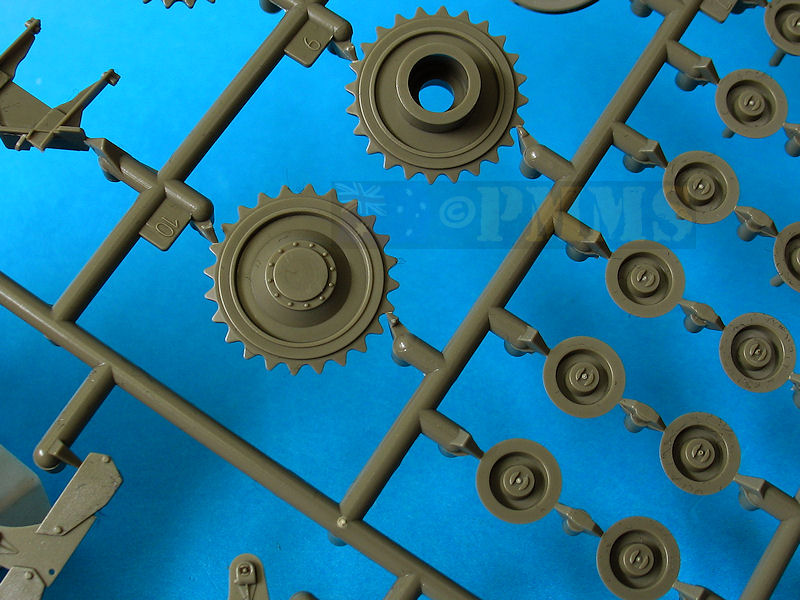
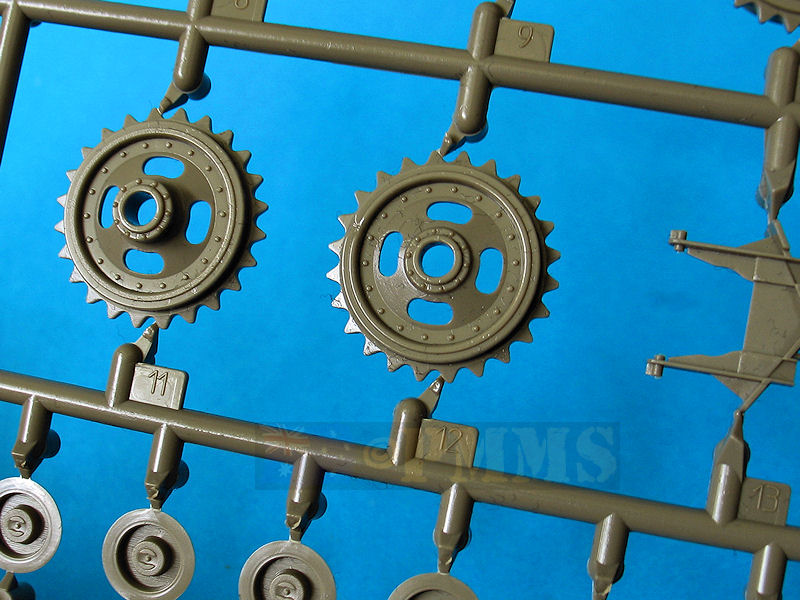
Detail on the idler wheels and drive sprockets is also very well done and the wheel dimensions also match the plans perfectly, there should be lightening holes included in the front idler wheel inner hubs if you wanted to add these but they are all but hidden from view after assembly in any case. Each wheel is in two halves with very crisp detail not requiring any additional cleanup other than the sprue attachment burs on a couple of the teeth and there is a vinyl poly cap trapped between the two drive sprocket halves for easy fitting to the drive axle. The final drive housing is also a separate part that is attached to the hull side plate with the idlers having two mounting panels attached to the front of the side panniers.
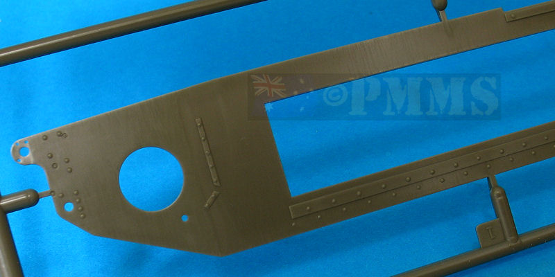
When attaching the assembled side panniers/suspension to the hull sides (parts A1. A3) you should temporarily fit the upper hull plate (part B25) between the two hull side as you glue them to get the spacing correct to ensure a good fit of the top deck later. This is important as gluing the hull sides into place without checking the fit of the top deck can result in rather large gaps between the hull sides and deck when you come to fit the deck later, so save yourself some grief and check this now.
Gluing the assembled suspensions to the lower and rear hull plates is very straightforward as the fit is very good if a little fiddly to get lined but once in place the fit is good. The rear hull extensions that fit over the drive sprockets are also nicely detailed and fit precisely onto place but you should note there are attachment brackets for the later fender bracings (parts E10) and if these are not fitted you have to cut off the mounting brackets from the hull extensions (parts C5, C11) as the instructions omit to mention this.
Also there are the elaborate mud scrappers that are trapped between the hull and outer panels as these are fitted and you shouldn’t glue these as they are designed to move a little, just watch that you fit the scrappers the right way up as it’s easy for these to be added upside down.
Other details added to the hull sides are the alternate separate crew entry doors, one of the original type and another with the appliqué armour added to use with whatever configuration your are building. The doors have additional inner face detail if you wanted to show these open but as there is no internal detail its better to leave these closed, there is also fine rain channels to add above the doors.
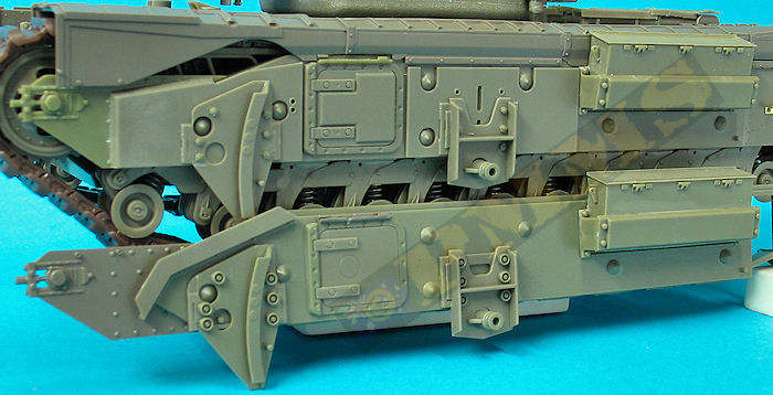
The large side armoured air intake trunks mounted on the hull sides made up of 5 parts each are the correct style for the Mk.IV with the smooth front panel and with the top mesh screen that has moulded mesh detail plus a choice of sheet metal cover.
There is the standard curved cover as seen on numerous Churchill’s as well as an angled cover in etched brass as an option as seen in a few photos of trials and serving vehicles, it should also be noted that many action shots show the cover missing altogether with the top mesh exposed which gives a third option for displaying the trunks.
Assembly of the trunks was straightforward and the fit to the hull sides very precise with the trunks in the accompanying images just sat in place not actually glued such is the good fit and at the back is the smoke generators made up of three parts each (1 etched) and the air deflectors along with the tow shackle and mounting plate with the fit of these parts not causing any problems.
The upper air intake grills are also separate parts but there is quite a bit of cleanup needed on these before attaching with the fit off all the real panels being very good not requiring any trimming other than some very fine flash on a couple of mating surfaces that would probably be dissolved by the glue in any case as its really very minor.
The large H mounting on the hull side has a separate mounting plate for Type B and is added to the appliqué side armour for Type A and added to the H mounting are eight separate small bolt heads, these are different depending on the Type being built so check the instructions closely for the right bolts heads to use.
The two part forward curved mounting bracket also has a separate mounting plate or the appliqué armour depending on the Type and the separate retaining bolt heads are again different for each Type as they are for the larger side H mounting plate.
You will also need to take care with these small bolt heads as they are quite small and being round very slippery to get hold of and there are no spares so watch how you handle these to avoid any disasters, but the resulting detail definition is worth the extra effort fitting the small bolts.
This kit periscopes are the same as the previous Mk.III/IV kits but unfortunately the periscopes indicated in the instructions to use (parts P13) are again those used on the Churchill Mk.VII and not the Mk.IV unless it’s undergone a major rebuild which is unlikely due to the lack of other upgrades.
You should use the earlier periscope parts E33 and E34 along with the clear parts H1 and H2 for the correct “standard” Mk.IV periscope configuration. Note these periscopes rotated on the real vehicle and there is the full inside periscope (part H2) but this is difficult to see after assembly so if you have the hatches closed save yourself some time and parts H2 completely.
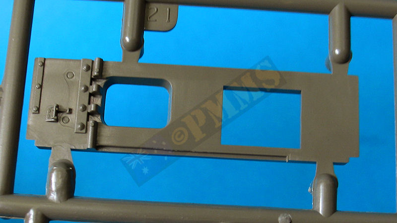
The right crew hatch has the outer frame with a more rounded profile (part L39) and you should make sure you use this and not the original which is still in the kit. The separate hatches have inner padding without any pin marks to contend with as well as very small separate etched inner fittings and plastic latch handle and separate outer grab handle for good definition. The fit of the frames and hatches is very good not requiring any trimming at all and you can again leave the hatches open if you wish to include any of the resin crew figures available separately.
The left hatch is blanked off and the small sliding reload hatch included and this has separate small etched hatch guides that will allow the separate small hatch to slide open or closed on the final model if careful with the glue during assembly. The etched parts in this kit are on a revised fret applicable to all the AFV Club Churchill kits and have the brass parts slightly thicker than on the previous frets, resulting in the locating groove for the hatch guides being fractionally too narrow requiring a bit of filing of the etched guide to fit the groove better.
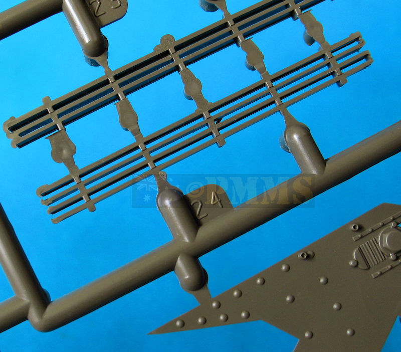
Moving to the glacis this has very fine details including with the bullet splash guards being especially finely done and this plate has to added before the lower front plate as you have to slide the glacis into the slots on the insides of the inner idler mounting plates but the fit is very snug once in place. Added to the glacis are the two part head lights but you may want to leave these off until later to avoid damage at this stage?
Fitting the lower front plate was snug but you should test fit as a little trimming of the inner raised blocks on the inner idler sponson mountings (parts A19, A20) may be needed for the front plate to sit flush with the glacis, as noted this may depend on the placement of the hull/side sponson parts during the earlier assembly so check the fit before gluing. Added to the front plate is the central tow shackle and mounting bracket that fits without any problems.
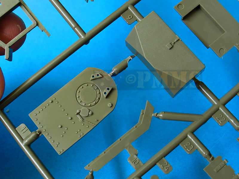
The driver’s plate has a separate main vision port hatch with the smaller bolted vision flap also separate so you can show either the full hatch or just to port open as was often the case, there are additional smaller plastic and etched parts added to the hatch as well as the visor on the inside.
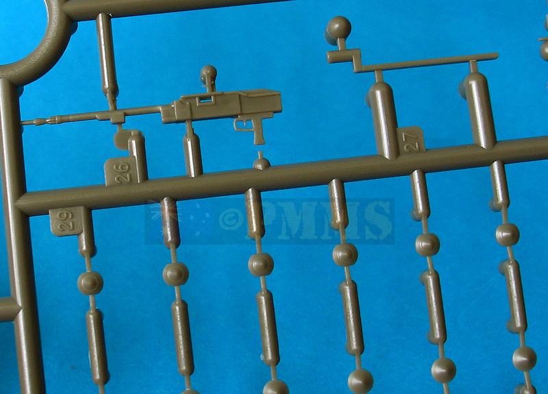
On the left is the co-axial BESA MG in full with an etched part for the jacket although the barrel will need to be drilled out for a better appearance. The BESA then fits into the armoured cradle that is held in place by two securing brackets that allow both elevation and traverse. The BESA is quite nice but the flash suppressor is undersized and not drilled out and could be improved with the use of an aftermarket item, I have used here the new full BESA MG with metal barrel from, SKP Model (set #SKP 022) this includes the barrel support in resin as well as the receiver.
Added to the panel is the outer armour block around the co-axial MG with the fit of the driver’s panel being very good but you should fit the main driver’s panel in place before adding the additional armour block as this partly sits on top of the glacis.
Added each side of the glacis are the inner fender plates that also hold the wooden jack blocks and the plates are different for left and right so watch this when fitting with the fit of the main top deck is very good between the driver’s plate, the side panels and the rear engine deck plate proving you checked the side plates as mentioned earlier.
The rear engine deck hatches also have separate fine plastic grab handles and fit snugly to the deck cut-outs and being separate will allow the easy inclusion of engine detail should an aftermarket interior become available?
Added on the deck are the two exhaust pipes made up of six parts including the sheet metal covers which are moulded quite thin for a good appearance with these all fitting neatly in place without any problems.
There is also an additional engine deck plate at the back of the main deck and this again has separate fine grab handles and fits snugly in place without any trimming needed. The pioneer tools supplied have their brackets moulded with the tools and you need to drill out the tool locating holes in the deck. Replacing these brackets with etched items from any of the etched sets already released for the previous Mk.III/IV will improve the look.
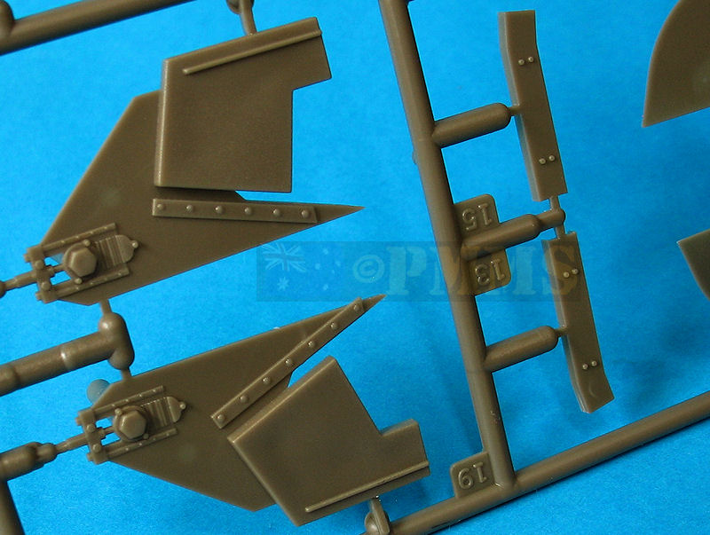
Also included for the rear are two spare suspension bogie assemblies that have the same springs as the main units and assemble in the same manner but references indicate this configuration was not universal and only one unit actually bolted the spare bogies to the fenders as depicted for the D-Day landings. Others units appear to have just carried the spare bogies unattached on the rear deck and referring to references will determine the appropriate position for the spare bogie units with the decal sheet indicating these spare bogies only used for one of the marking options.
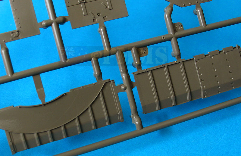
The final parts for the hull are the fenders which are provided in six main segments plus the side fender plates at front and back as well as the rubber (in plastic) mud flaps added to the front fenders, there are also alternate parts at the back depending if you are building the later or earlier style fenders.
Providing these fender segments as separate parts is a great bonus not only for easier fitting but to allow you to build the model with any number of fender segments missing as is often seen in photos of battle weary Churchill’s. Period photos of the Churchill Mk.IVs of all types also show the front curved section of fender over the idler wheels rarely if ever fitted and leaving these off would be the preferred option.
Again test fitting of the fender sections is essential and I actually glued the sections together to form one long fender before final fitting to the model as this will assist in aligning the fenders correctly, obviously these were test fitted numerous times during assembly to get things right but the end result is easy final fitting.
Added to the rear fender segments are the storage racks for four water cans and these have additional etched brackets for a nice appearance.
Before fitting the fenders you have to add the full length vinyl track which have quite good details for the medium but there are some pour plug marks on some links that are difficult to remove and joining the tracks together is an interesting exercise as there are no actual pins to join the ends and normal plastic cement has no effect. I tried using a medium thickness cyanoacrylate but this came apart while stretching the track around the idler and drive sprocket and ended up heat welding the two ends together. This resulted in a bit of link distortion due to the lack of join pins but this can be easily hidden under the fenders or at ground contact with the tracks fitting very nicely around the idler, drive sprocket and the road wheels with a slight track stretch to make for a snug fit.
The alternate B.T.S 3 Heavy track should also be fitted before the fenders for obvious reasons and I’ll refer you to the review of those tracks in set #AF35183 for the full details but as mentioned in that review the fit of the assembled tracks to the kit sprockets is not the best and I actually cut away the teeth from the idler corresponding to the track placement to bypass the fit issues mentioned.
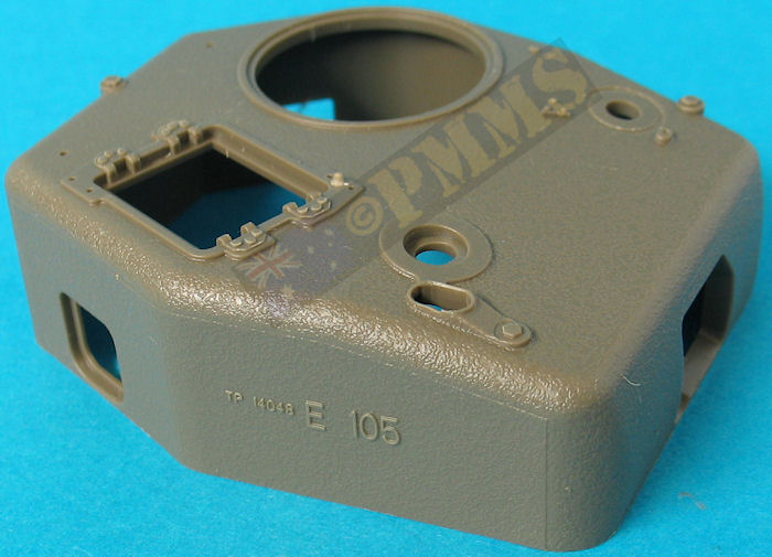
The turret shell has openings for the gun and co-axial BESA mantlet, separate periscope and ventilator, pistol ports, crew hatches and open 2" bomb thrower port.
Dimensionally the turret matches the available data very well give or take a fraction here and there and is well within acceptable tolerances as does the turret shape, the only quibble is the corners and top edges appear a little sharp but this may just be a visual thing on the scale sized turret?
showing only minor discrepancies.
For the single periscope the instructions show to use the correct periscope parts E33 and E34 along with the clear parts H1 and H2 but again the inner part of the periscope is not visible after assembly so not fitting this will save a bit of work..
The flat Commander’s cupola is nicely done with separate hatches that have inside padding without any pin marks as are the Loader’s hatches along with additional smaller inside latches that will need care removing from the sprues and in fitting. There are small securing latches added next to both the Commander’s and Loader’s hatches which have quite large sprue attachments for their size and the instructions have the wrong part numbers for the Commander’s hatch latches. These should be parts E16 and not E17 as indicated which are for the Loader’s hatch latches.
The cupola vision ports have separate covers but the edges are very thin and due to the sprue attachment being right on the edge these are easily damaged and care will be needed removing these from the sprues. There is also a small searchlight light added to the side of the cupola made up of two clear parts.
The etched vane sight in thin brass (part G21) is the later type not usually associated with the initial Mk.IV turret in the kit but again the more appropriate vane sight is still included on the etched fret (part 13) and you should use this positioned in front of the ventilator cover. Just a quick note on the ventilator cover, the kit cover is the early type with later covers being flatter in profile and slightly larger in diameter, some period photos of early Mk.IV turrets show both the early and later types (not both at once obviously).
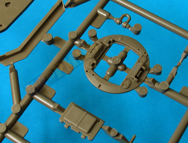
The circular No.19 Radio antenna base provided is very well done for an injected plastic base but unfortunately is oversized somewhat and there is little you can do other than replace this with an aftermarket antenna base of the right size if this is of concern. I have used here the excellent antenna base from Lionmarc Designs (set #LM60009) which also adds additional detail over the kit base.
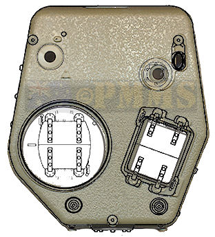
At the back is the three part turret box that goes together well and attaches to the four raised bosses on the rear turret wall, take note as the original box is still included on the sprues so make sure you use the correct parts as indicated in the instructions. The turret ring is designed to clip into the hull top turret ring without the usual notch cut-outs used on many kits. This makes for the cleaner appearance but it’s not easy to remove the turret after fitting so you may want to leave this off until towards final assembly.
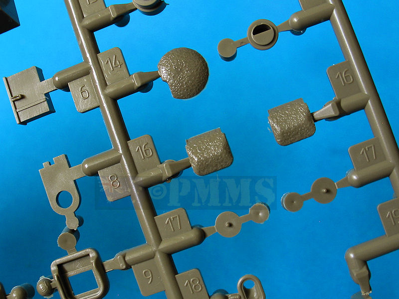
Other items added to the turret are the two fire extinguishers either side of the rear box and the signal flag container which is nicely textured plus the two rod antenna made from stretched sprue.
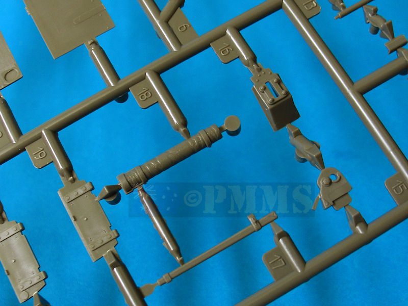
A full internal breech is provided for the Petard and is nicely detailed with the main parts included and this is fitted to a modified gun mantlet that has the BESA armoured cradle as a separate part with the full BESA MG with etched guard added. As with the hull MG the flash suppressor is undersized and I replace the barrel with that offered by LionMarc Designs/Passion Models to improve the appearance.
The Petard barrel assembly is made up of 12 parts (1 etched and 1 spring also) and you can depict this in the firing position or broken for the upright loading configuration depending on how you want to depict the mortar tube.
You have to be extremely careful removing some of the small parts from the sprue or you will loose them, in particular there are three very small discs, parts L38 x 2 and L23 used to hold the small spring in place which is about 0.8mm in size, so take extreme care with these.
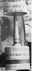
Detail on the Petard is very well done with the barrel tube a single hollow moulding that includes raised casting numbers on the outside and most impressively the four raised rifling strips on the inside of the tube which is such a prominent feature of the Petard barrel tube. There is a little fine flash on the end of the barrel and a fine mould seam to be removed which is easily done.
You are provided with a small spring for the barrel mechanism and as this is a real spring you need to take the appropriate care when fitting to not launch this into oblivion in the process but it gives excellent detail definition over what could be achieved with a plastic spring. Assembly of the mortar is a little fiddly due to the fine parts but with care there shouldn’t be any problems?
The curved guard over the BESA barrel is moulded commendably thin and doesn’t need any trimming which is often the case with such parts and the fully assembled Petard looks most impressive.
The full mortar assembly is attached to the insides of the lower turret ring with the two notched brackets but you should not attach the outer mortar assembly before fitting the turret shell parts together as the mortar barrel assembly will not fit through the turret front opening as with the 6pdr gun.
Also included are two 290mm Petard mortar rounds made up of 7 parts each that would only need the circular rear fins to be thinned a little for a better appearance but unfortunately the prominent stencilling seen on the actual round is not included on the decal sheet. The assembled mortar round will also fit snugly inside the barrel tube if you wish to depict the Petard loaded and ready to go.
|
The standout feature again is the superb rendition of the complicated Churchill suspension that allows for fully articulated suspension if you wish. The metal springs provided look very much in scale adding to the final appearance.
Other details are very well done and the fit of the parts good overall but care is needed with the position of the hull side panels for the hull top fit as outlined above as this has potential to cause problems for the unwary. As with any kit there is scope for improvement and adding additional detail but the base kit is very well done.
The kit is not for the inexperience modeller due to some intricate assemblies and small parts but overall will build into the basic Mk.IV AVRE nicely and opens the way for any number of aftermarket add-ons for the many specialised engineer suites added as with the real thing.Rating 9/10.
Click on thumbnails for larger view


Sprue detail images


Build detail images
Close new window to return to review
Armour in Focus Profiles - The Churchill Tank
 |
Mr. Churchill's Tank See review for details. |
 |
Churchill vol.1 GUNpower 26 By Leszek Moczulski Published by AJ Press ISBN 978-83-7237-194-9 |
 |
Tamiya Photographic Album No.3 Has some excellent line drawings of the Mk.III/IV hull, turret and smaller details as well as full walkaround of the Mk.VII. |
 |
Churchill Infantry Tank 1941-51 Good overall coverage of all variants of the Churchill. |
 |
the Funnies A History with scale plans of the 79th Armoured Division Geoffrey W. Futter ISBN 0 85242 405 1 Is out of print and may be hard to find but has a detailed coverage with 1/76th scale plans of all the specialised vehicles used by the 79th AD from D-Day onwards. |
