
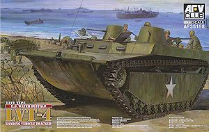
LVT-4 Water Buffalo (Late type)
AFV Club 1:35 Kit No. AF 35198
Review by Terry Ashley
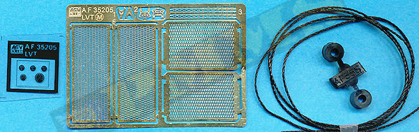
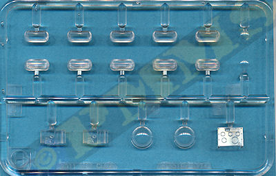
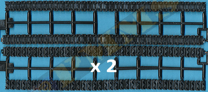
The kit features a fully detailed front crew compartment with transmission but unfortunately very little of this detail can be seen after assembly and there is a choice of three types of cal.50 MG shields. The kit consists of 433 parts in olive drab plastic, 17 clear plastic parts, 10 etched brass parts, a small clear sheet with instrument dials, 4 sections of soft vinyl track and a short length of twine plus the decal sheet and 20 page instruction booklet.
I don’t have any actual 1:35 plans of the LVT4 but the overall dimensions match perfectly to the LVT2 from which it was derived included in the Letterman Productions books and manuals on the LVT2 edited by the late David Harper.
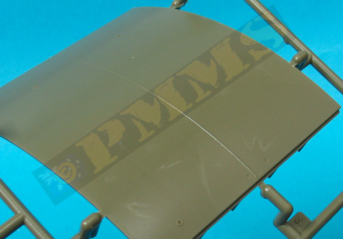
The standard of moulding is very good overall with clean crisp detail and just the odd bit of fine flash on some parts and bare minimum of pin marks that can be seen after assembly, those present are quite shallow and easy to remove if need be. On my kit there was an issue with minor warping of some of the larger (longer) parts and these will need to be straightened before assembly, a few of the assembly steps were also done differently to avoid any major issues due to this as explained below. As mentioned this is basically the same kit as the early version and this review is also the same as for that kit with just additional comments for the revised parts included in this later version.
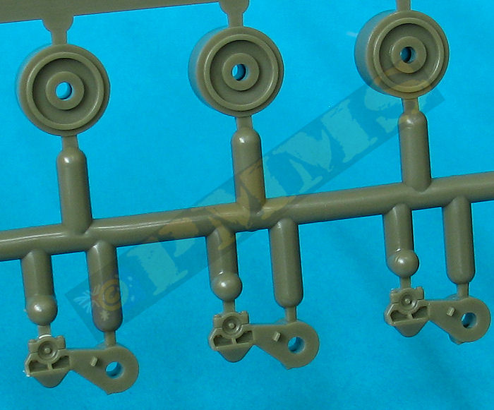
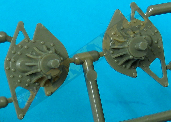
Attached to the outer sponsons are the rear idler units that include the idler wheels that have excellent detail on the two idler discs as well as the separate idler adjustment mounting on top of the sponsons. The two return roller assemblies fitted to the top of the sponsons are also nicely detailed without any assembly problems for these or the idler mountings.
Added under the sponsons are the rear most road wheel and the forward two part track guides, the instructions show to only fit one half of the guides but there is a small amendment sheet in the box showing to fit both halves of the guides (parts A16. A17) so don’t forget to see this.
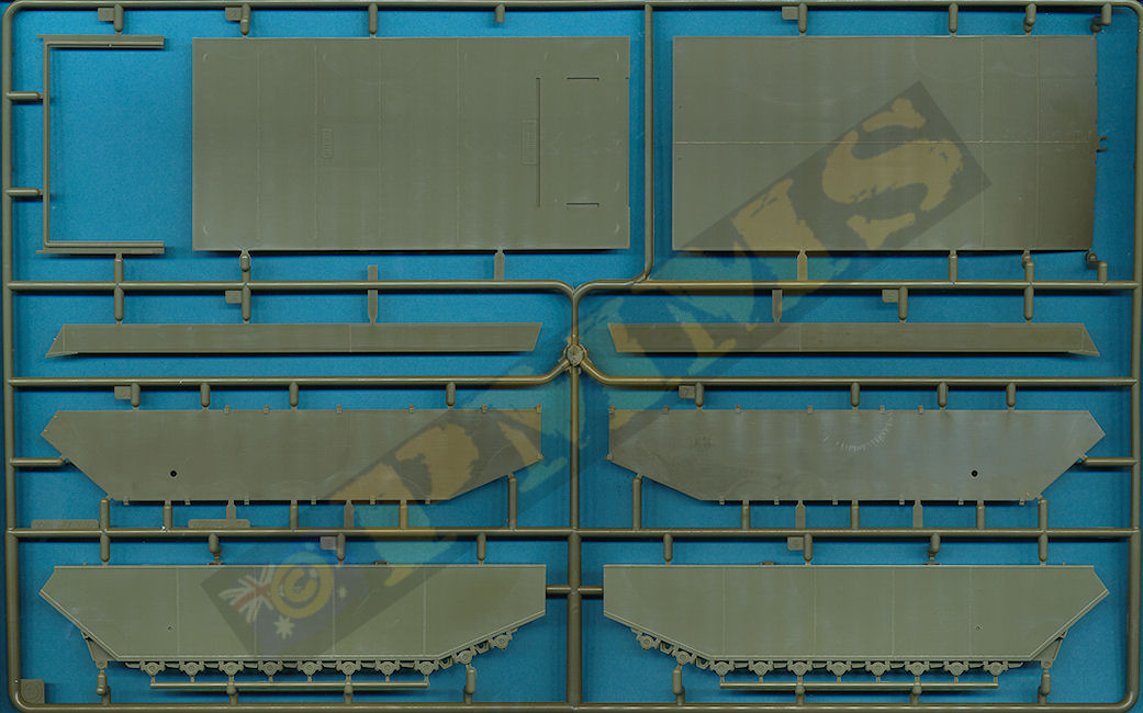
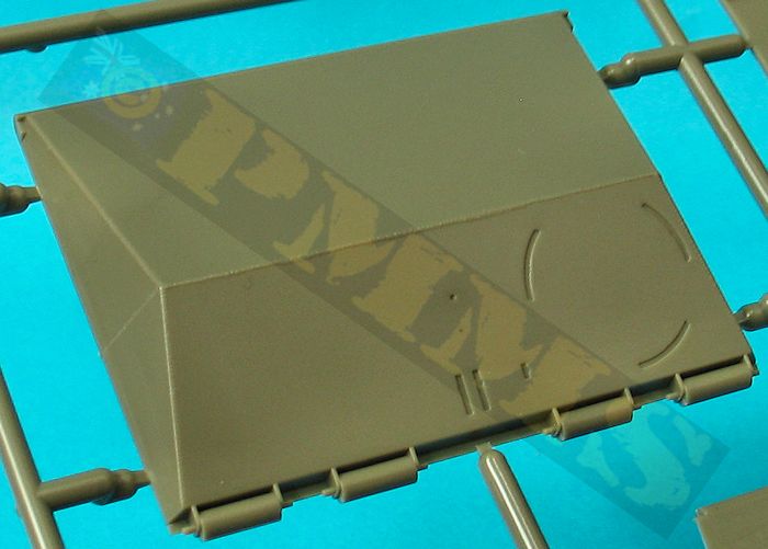
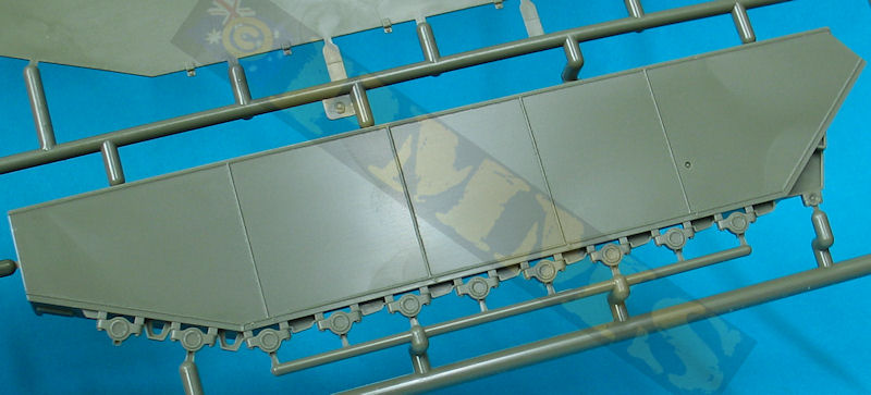
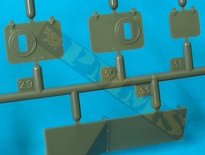
The kit also includes the additional sponson armour panels fitted to later LVT4s and building the kit with these fitted would be the most appropriate as indicated in the instructions.
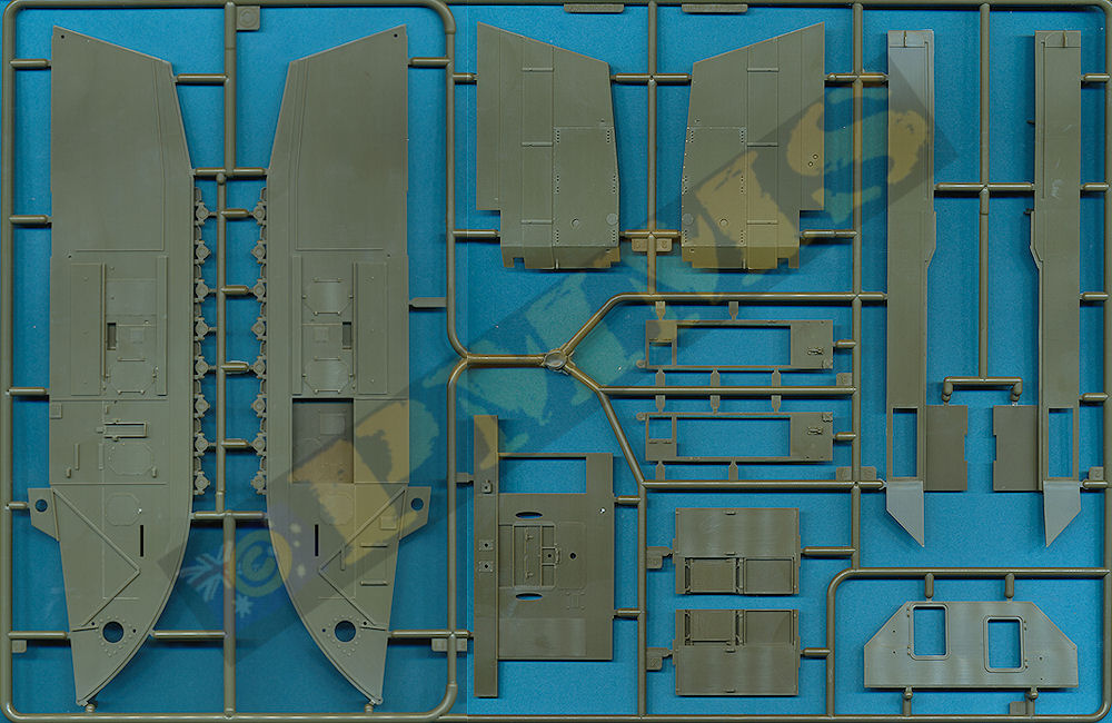
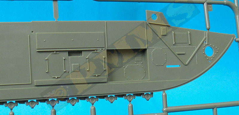
Assembly of the hull sides is quite straightforward with good fit of the parts although some joins will need to be held firmly together while the glue “grabs” to ensure the best fit especially around the areas where the parts needed straightening but all fitted well with due care.
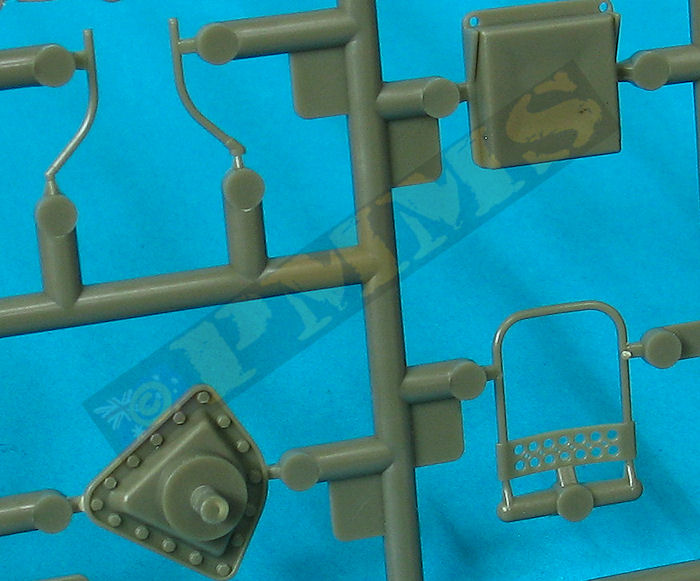
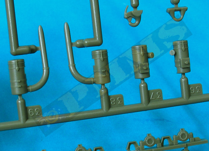
Inner detail is impressive with smaller interior details such as the attachment rings on the lower sides, separate fire extinguisher on the right side and the separate doors on the upper storage lockers, note also there are alternate mooring posts and small holes will be needed to be drilled for one of the options as indicated in the instructions. Fine etched mesh is also provided for the top engine bay screens for a good appearance although you can’t actually see these screens as they are under the top hull extensions.
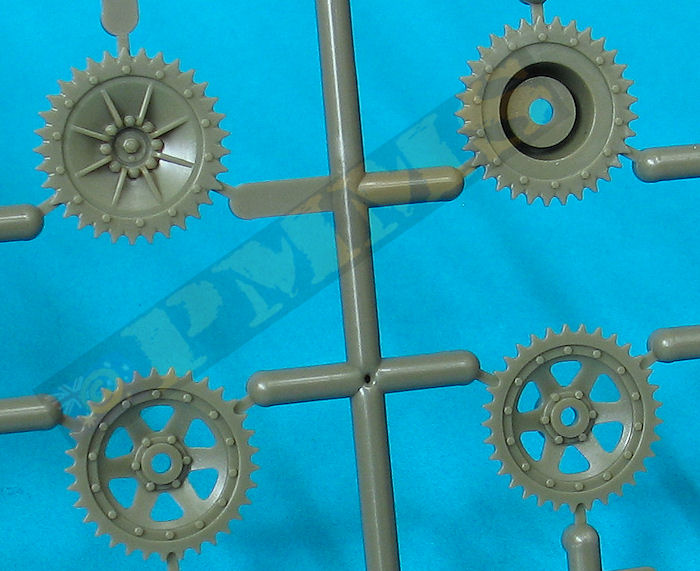
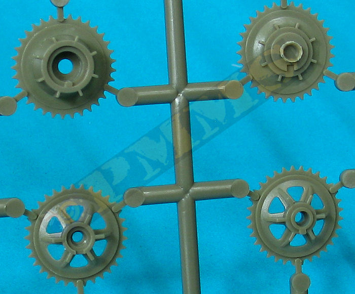
Each of the 20 suspension bogie units is made up of three parts plus the road wheel for excellent detail definition with the drive sprocket discs also having excellent dish and teeth detail with a small vinyl cap trapped between the halves for easy fitting to the separate final drive axle mountings attached to the hull sides.
As you fit the outer sponson to the hull sides the bogie units are trapped in place on their respective axle mountings without any problems , note there are quite a few large ejection plugs on the hull sides but these are hidden one the sponsons are attached so don’t be concerned with the initial appearance of the plugs. You will also need to ensure the parts firmly click into place before gluing as it can seem they don’t fit together too well initially as there are quite a few areas that have to mate together to get the perfect fit but once in place the fit is excellent.
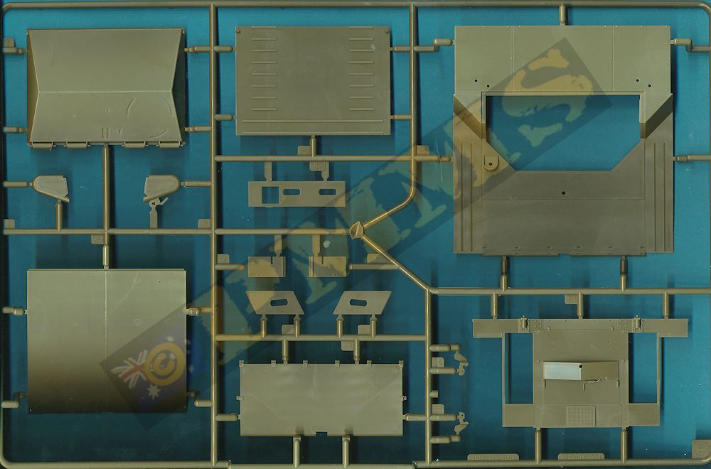
At the back are 8 part water boxes that fit together precisely with a little care to form excellent representations of the actual boxes and these are attached to the rear hull sides without any problems.
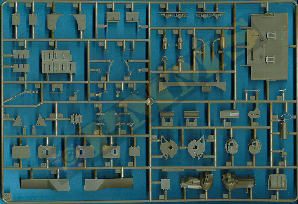
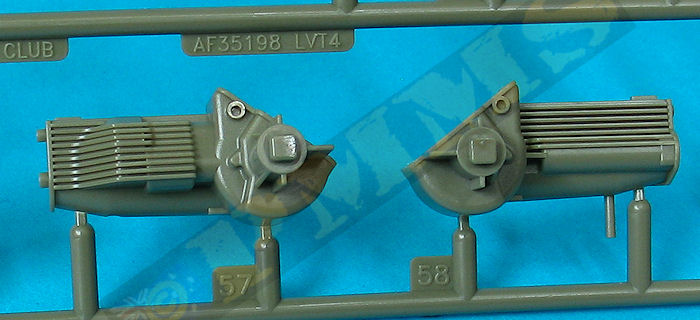
The engine bulkhead has separate air cleaners although the engine compartment is fully enclosed without any engine included while the crew compartment hatches are all separate allowing you to show open to see the interior detail. The new rear bulkhead has larger openings and some other small detail changes for the later type in the kit.
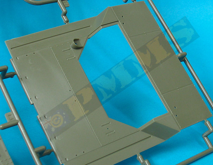
The compartment floor and transmission is attached to the front curved section of the lower hull and this is turn is attached the rear lower hull/well deck floor, these parts (D2, D3) are sandwiched together to for the lower hull. There are ribs inside both of these parts that are mated together but it is advisable to only glue the front two ribs initially as you will need to align the rear section of the parts to the inner hull sides during the final assembly. If the lower hull parts (D2, D3) are fully glued together there will be no movement to allow for any alignment adjustments during assembly due to minor warping of the large flat hull/floor or as a consequence of the gluing process and leaving unglued until final assembly will allow for any minor adjustments to fit correctly.
Fitting the lower hull/floor and the two assembled hull side panels is very precise but you will need to manoeuvre the parts to get all little nooks and crannies aligned correctly as there are again quite areas that need to align for the best fit. But with a little patience and manoeuvring and taking into account the above precautions regarding the lower hull plates there shouldn’t be any problems encountered and once assembled the inner engine compartment bulkheads can be added as per instructions. I actually added the engine compartment bulkheads before fitting the sides as this gave more room to fit the panels but this is up the individual, there are additional etched screens added to the side panels and again the fit was very precise.
The crew hatches have full clear plastic periscopes on the right hatch as well as inner and outer grab handles, the left hatch is solid without the clear dome of the early version but there are a couple of very small pin marks to deal with should you show the hatches open? Additional detail parts added are the head lights and guards; various grab handles and the mooring posts with the top hull fitting neatly to the lower hull, there were small gaps at the top side joins that may need attention but this will depend on the fit of the other hull parts along the way so make sure everything fits as snugly as possible before gluing. There is also the additional add on armour panel added under the bow if required, if you don’t fit the armour there are two small locating holes on the lower bow that will need filling.
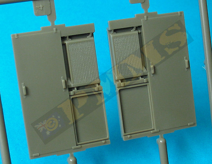
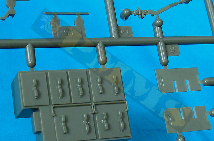
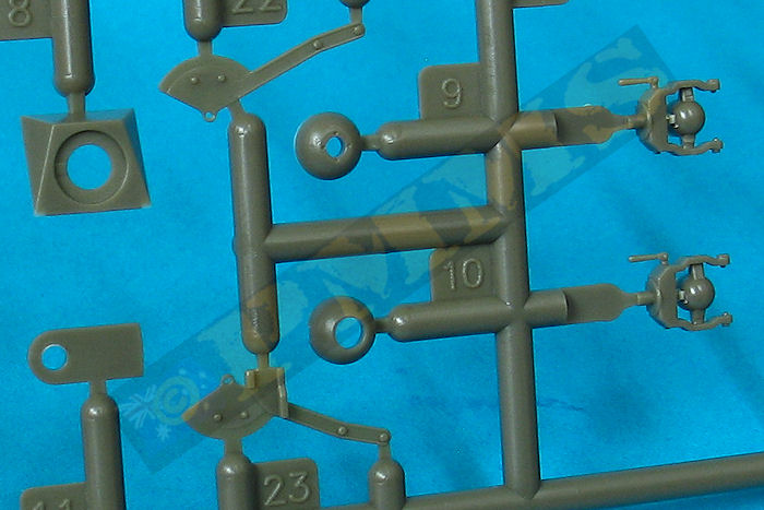
The two rear ramp winch/storage compartments have separate top panels with additional separate doors and you should only attach the left side (or right side, but not both) at this stage along with the ramp cable (thread provided) as you have to slip the thread through the ramp and into the opposite side compartment before fitting the other compartment top panel. As you fit the compartment tops the rear weapons mountings (parts K28) are trapped into place allowing the mount to rotate, note there is a pin mark to be removed from the mounting and also some early mountings had a single lightening hole in the middle of the bracket so instead of removing the pin mark you could drill a hole where the pin mark is to represent the earlier mounting if you wished?
The later tube style outer ramp extensions have small cable guide brackets and grab handles added and once the thread is slipped through the cable brackets and ramp the inner ribbed ramp floor can be glued into place before moving onto attaching the ramp to the hull which is without doubt the trickiest part of the assembly.
The ramp hinges are quite complicated with 8 separate small hinge brackets attached to the rear hull and over the pins on the base of the ramp and care will be needed as this process will test your patience getting all eight brackets aligned while holding the ramp in place. I actually lightly glued the brackets to the hull and then splayed these apart while aligning the ramp hinge pins and then straightened the brackets to fit over the pins applying a little more glue to secure the brackets in the proper position and allowing to dry completely before proceeding.
Once the ramp is attached the thread is pulled through so it is taught with the ramp lowered and the other end is fitting inside the top winch compartment and the top panel added while trapping the weapons mounting in the process as mentioned above. If showing the ramp raised the thread cable will need to be fed back into the winch compartments, if you plan on gluing the ramp in the closed position you can bypass the cable and glue the ramp hinges in place alleviating much of the pain assembling the working hinges.
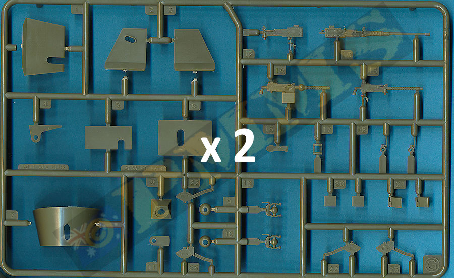
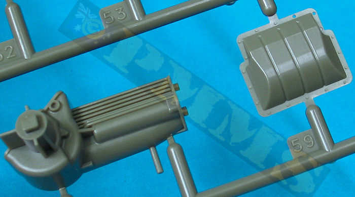
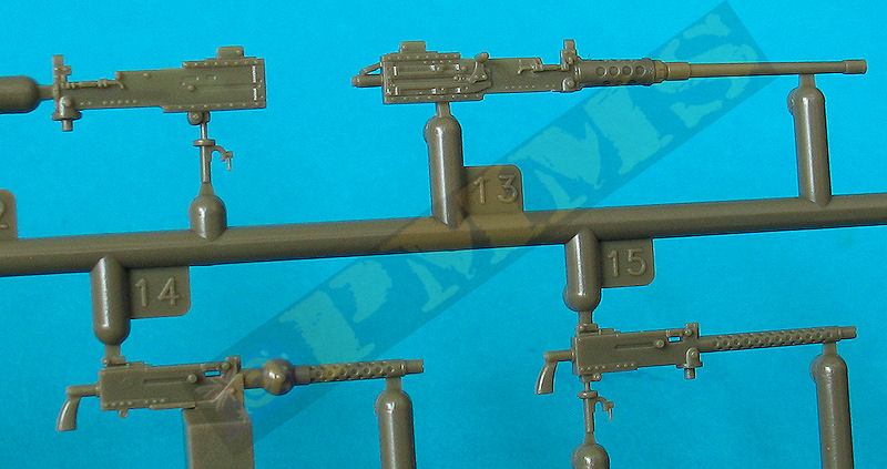
The D36960 type cradle, pintle and ammunition box assemblies are nicely detailed made up of four parts for the cradle and two for the ammo boxes and build into excellent representations of the actual cradle assembly with fine etched chain provided to add to the cradle although the instructions don’t mention the chain, it is there lurking on the etched fret.
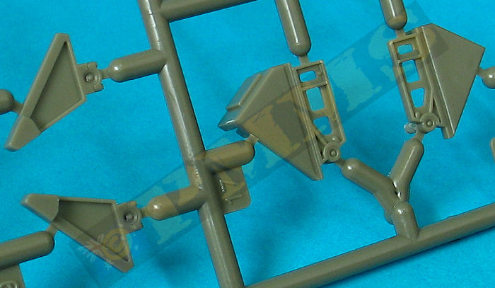
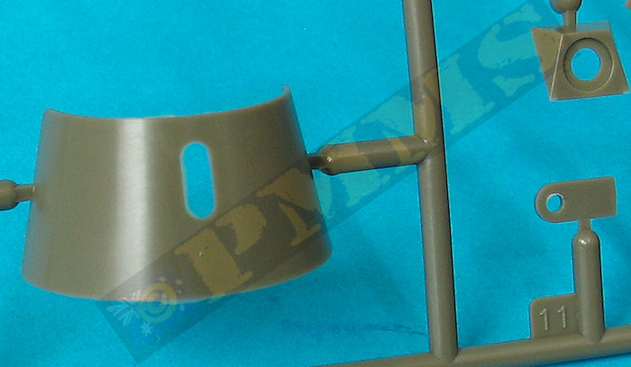
There is a choice of three styles of cal.50 weapons shields, the simple flat plate, the curved shield and the enclosed box shield with all three seen on various period photos of the LVT4 in action. There are a few shallow pin marks on the inside of the shields to be eliminated but nothing excessive.
|
There was some minor warping on the larger hull parts that will need to be dealt with and this can affect the final fit of the parts so care is needed to ensure everything is aligned correctly before gluing, especially when fitting the major hull panels together. There is scope for ill-fitting parts if not careful but good fit overall with due care.
This kit of the later LVT4 includes the additional late features nicelydone and will build into an impressive model but isn’t for the inexperienced modeller but is a generational leap in quality and detail over the now elderly LVT4 kit from Italeri.
Rating 8.5/10
Click on thumbnails for larger view
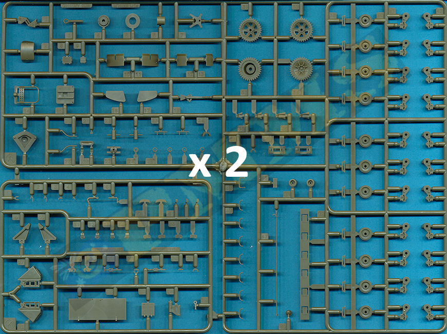
Sprue detail images


Build detail images


Close new window to return to review
| Ground Power Magazine #115 - 12/2003 GALILEO Publishing Co.,Ltd  |
Model Tech Manual LVT2/LVT(A)2 Letterman Publ. TM-LP010  |
US Amtracs and
Amphibians at War 1941-45 Concord Publications  |
| AMTRACS in action Jim Mesco Squadron Signal Publications ISBN 0-89747-298-5  |
Amtracs US Amphibious Assault Vehicles by Steven Zaloga Osprey New Vanguard 30  |
