
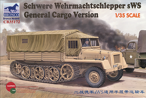
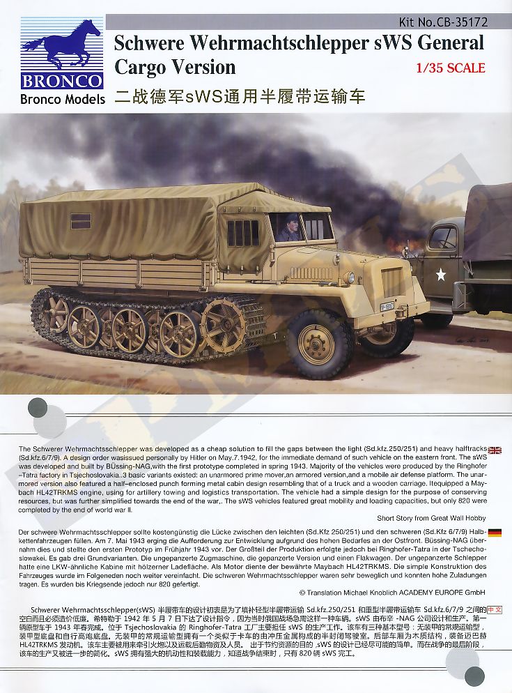
Schwere Wehrmachtschlepper sWS General Cargo Version
Bronco Models 1:35 Scale Kit No. CB35172
Review by Terry Ashley
The sWS was powered by a 6 cylinder, water-cooled Maybach HL42 TRKMS gasoline engine generating 100 horsepower (75 kW) which gave it a top speed of 27 klm per hour (17.0 mph) on good roads with a load capacity of 4,000 kilograms (8,800 lb).
Later types featured an armoured cab and engine compartment looking similar to the Sd.Kfz.251 with fold down sides for the rear cargo bay. The armoured sWS was also used in two other configurations, one fitted with the 3.7cm FlaK 43 anti-aircraft gun on the rear bed and the Panzerwerfer 15cm Nebelwerfer 42 rocket launcher mounted over an armoured ammunition storage compartment built over the cargo area.
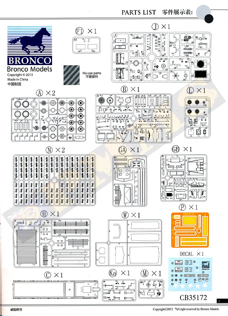
The kit consists of 15 plastic sprue runners and 1 etched fret with:
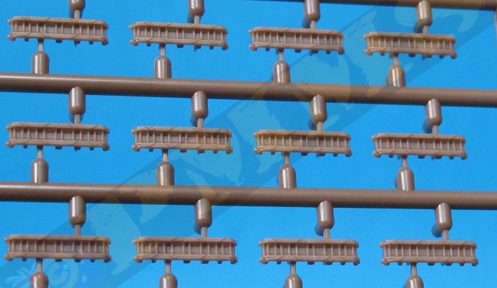
357 parts in light beige plastic248 parts in brown plastic for the individual track links
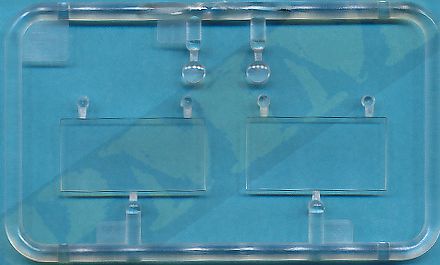
11 clear parts
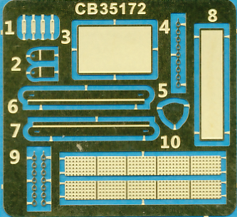
16 PE parts
1 decal sheet
1 x 16 page instruction booklet
The quality of the moulding is excellent with clean crisp details virtually free of any flash or pin marks and any present is quite minor and easily dealt with. There are the usual mould seam lines to be removed and as some of the parts are extremely small and you will need to take care removing these from the sprues and during assembly.
Dimensionally the kit measures up very well against the 1:35 plans in the Tank Magazine and Panzer Tracts No.12 books listed below with parts such as the running gear (apart from one issue as below), track and hull widths being spot on. There is also disagreement on some dimensions between the plans with the kit matching parts of one plan and parts of the other. So overall it sort of evens out and the kit certainly doesn’t look out of proportion in any way compared the available photos.
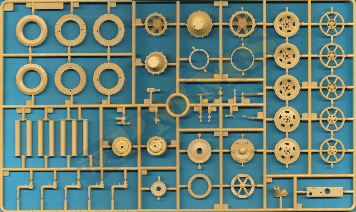
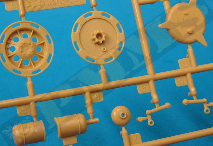
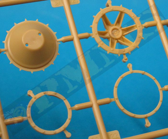
Included in the kit is a number of options including two styles of front wheel rims, two sizes of drive sprocket, the initial large and later smaller diameter sprocket as well as two styles of idler wheels, the initial spoke idler and the solid disc idler with the later style of road wheels which have the full dish wheels on the inside and spoke wheels on the outside of each wheel station.
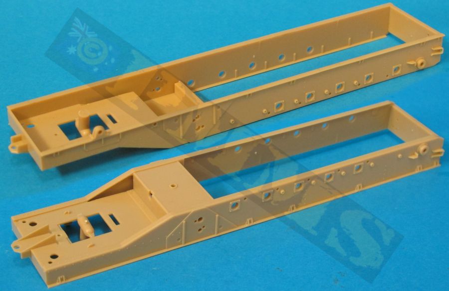
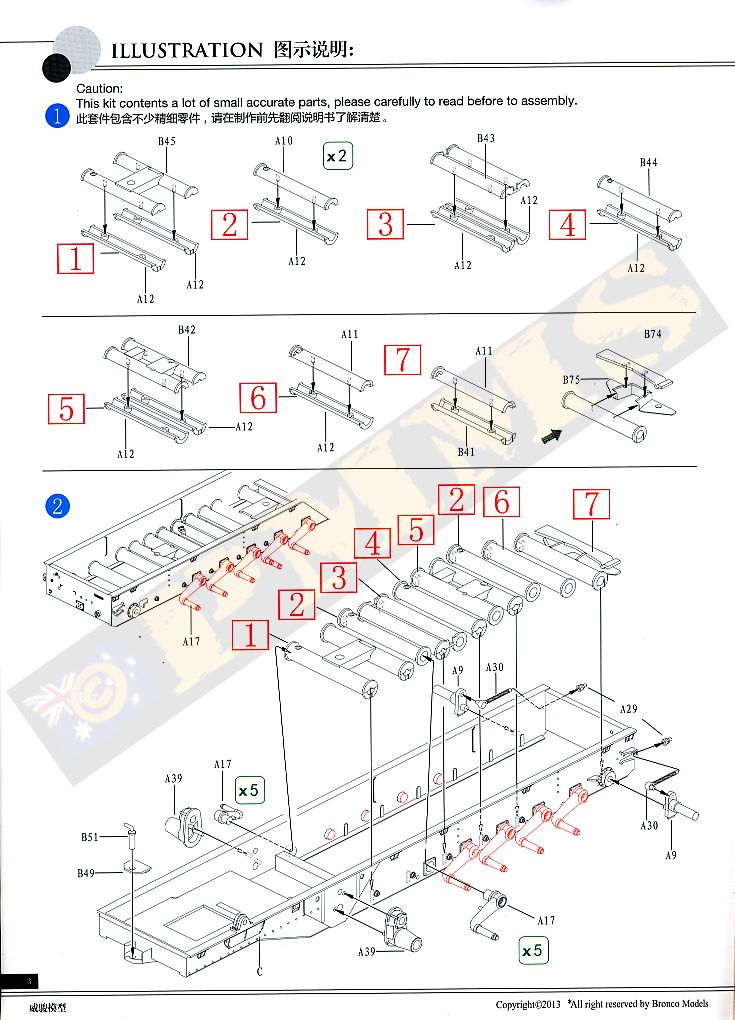
The kit is also broken down into sub-assemblies which can be built separately and brought together at final assembly which allows you to work on one while the glue/paint dries on another and this helps speed up assembly. The sub-assemblies are the lower chassis/suspension, forward cab/engine compartment and rear cargo tray.
Added to the chassis side are the 5 axles per side which have subtle cast texturing on the arms and you have to be careful removing the moulding seams so not to eliminate the texturing, the arms are hidden by the road wheels anyway so it probably doesn’t matter a lot?
The axle arms have a small pin to ensure they are all aligned correctly in the neutral position and if you wanted to articulate the suspension you just cut off the pin and reposition the arm.
At the back the idler axle mounting has a separate threaded adjustment bolt that fits through the hull bracket with a separate tensioning bolt and gives very good definition to the mounting. There is also a three part towing pintle, boarding step and compressed air valve as well as the towing pintle on the front of the chassis with separate pin.
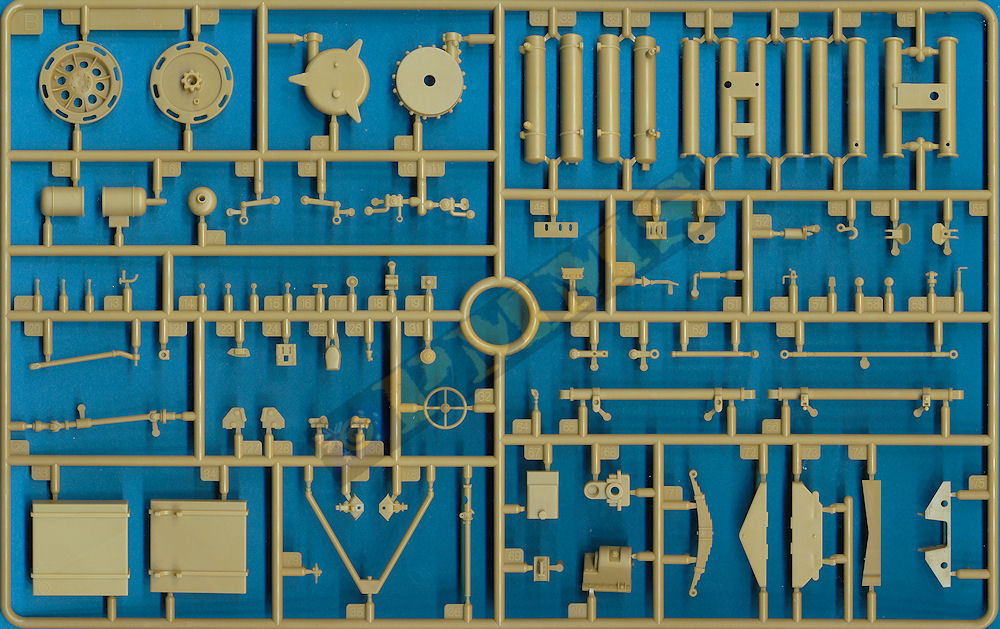
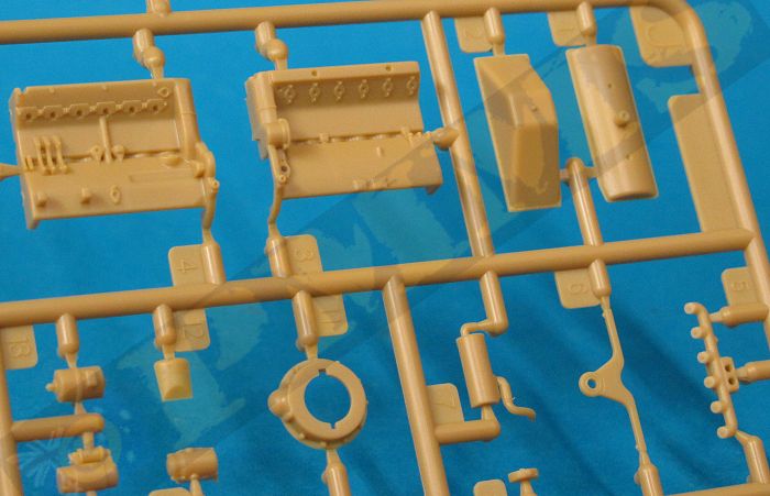
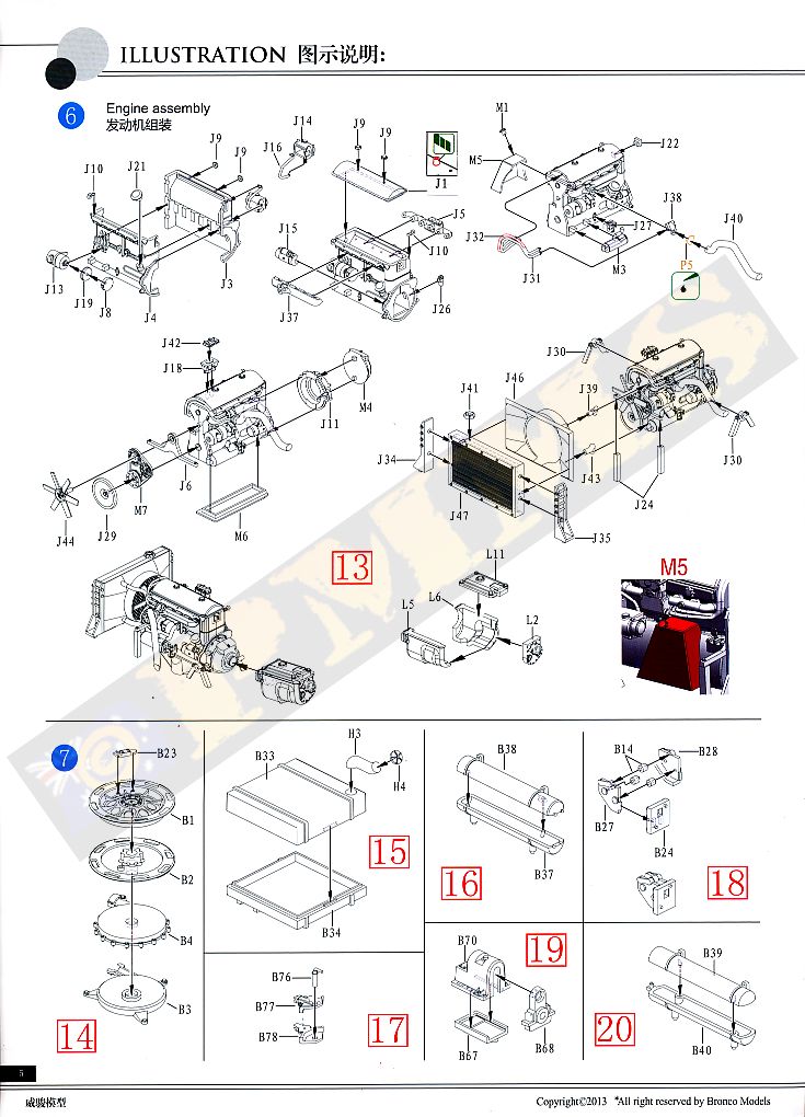
The kit includes the full Maybach HL42 TRKMS engine and transmission to fill the engine bay and this is where most of the kit alterations occur with modified parts to correctly depict the Maybach HL42 TRKMS as fitted to the sWS.
All the alterations from the previous engine in Bronco kit CB35070 which was basically that as fitted to the Sd.Kfz.10/250 series of vehicles are shown in the review of the separate GWH Maybach HL 42 TRKMS Engine for sWS set #L3522 and all these modifications have been included by Bronco for this kit.
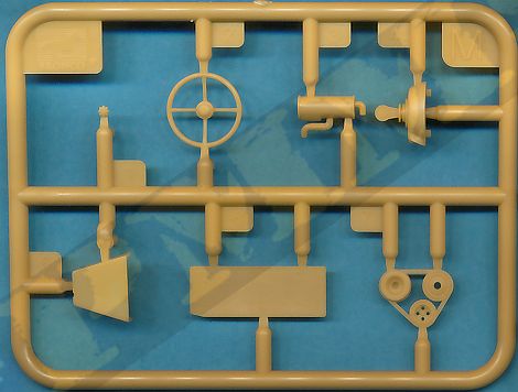
The engine is highly detailed with all the accessories such as alternator, carburettor, fuel pump, fan, belts with pulleys etc. as well as the large air cleaner, side mounted oil tank, intake and exhaust manifolds with their connecting pipes all included as separate parts.
At the front is a five part radiator assembly that connects to the engine by two large radiator hoses and a four part gearbox case added to the rear which connects to the transfer box and transmission with four ribbed brake discs for a very detailed and impressive assembly that fits neatly into the chassis bay.
The separate exhaust pipe fits to the exhaust manifold to mate on the inside of the chassis level with the outer exhaust pipe and muffler, unfortunately the inner exhaust pipe fouls on the steering rod (part B36) when fitted and you will have to modify the position of the exhaust pipe so it misses the steering arm.
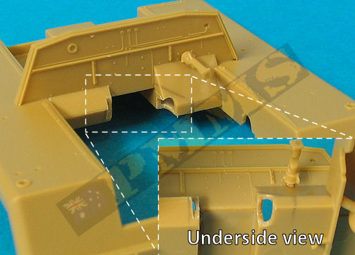
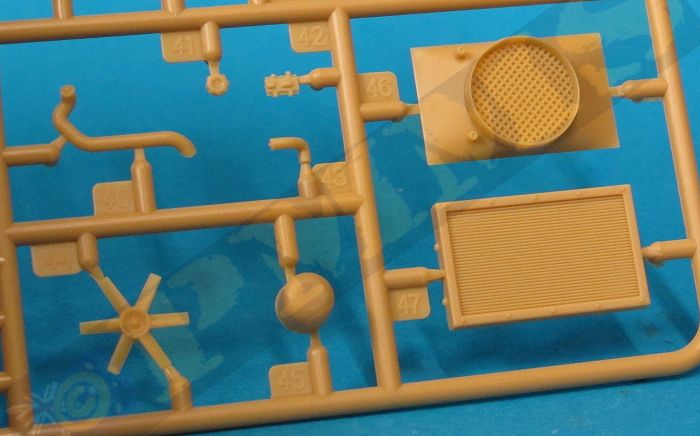
The sWS didn’t have an open engine bay with the bottom of the bay fully enclosed to prevent debris entering the compartment and the large square and smaller round holes will need to be filled in the kit compartment floor before proceeding.
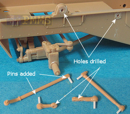
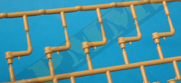
There are 4 steering linkages added to the left side of the chassis and as we have seen on some other kits these are not designed to be movable and once glued in place negate the workable steering?
This does allow you to position the front wheels at any angle as you glue the linkages for a bit of animation and it’s also a simple task to modify the steering linkages to make these workable for truly workable suspension if you wish.
This entails cutting the locating pins from the parts to fill the corresponding locating holes and when dry drill holes for the thin plastic rod pins (I used 0.6mm plastic rod) added to the appropriate places on the linkages. You then slip the pins through the holes and secure by heat melting the ends of the pins which results in fully workable steering.
This entails cutting the locating pins from the parts to fill the corresponding locating holes and when dry drill holes for the thin plastic rod pins (I used 0.6mm plastic rod) added to the appropriate places on the linkages. You then slip the pins through the holes and secure by heat melting the ends of the pins which results in fully workable steering. See images.
Holes drilled in chassis and linkages to take the pins added to the rods.
The pins are heat welded to secure in place.
Note; the locating pins are cut from the parts and glued into the locating holes before
drilling the pin holes.
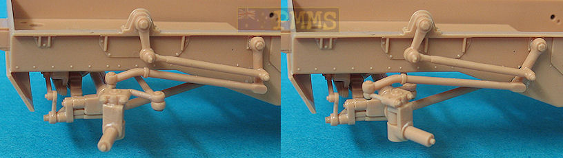
Modified steering linkages allow for full movement.
Steering with wheels added
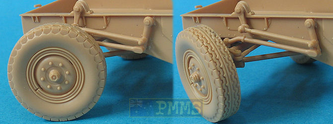
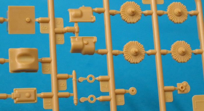
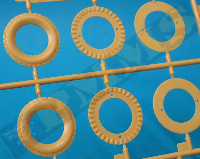
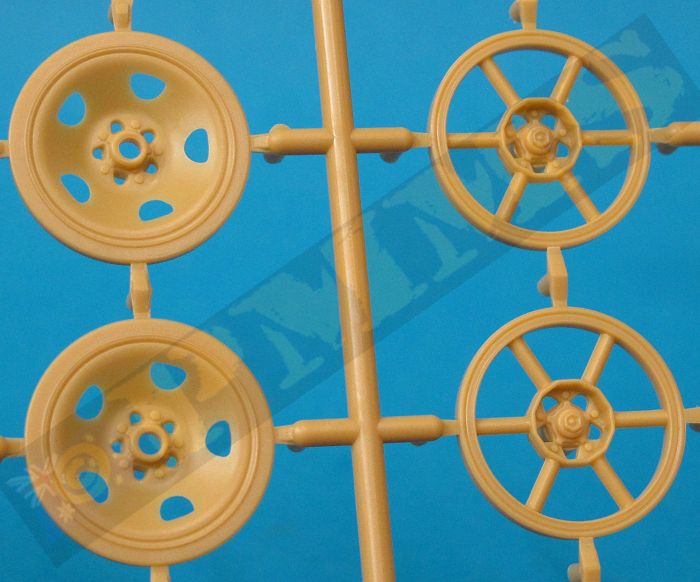
The front wheels have alternate hubs with subtle differences in the details such as rim bulge and number of lightening holes with both types seen in photos of the sWS so there is no real preference here as either can be used. The tyres are in six sections each which are sandwiched together for excellent representations of the tread pattern but you have to ensure the segments are put in the right order and also you should squeeze these together tightly when gluing to eliminate any gaps.
The hubs are a nice tight fit inside the tyres when assembled with the final wheels looking excellent with the well-defined tread pattern; the only thing missing is any tyre side wall embossing but apart from that are very well done wheels.
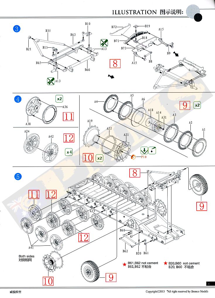
Each drive sprocket is made up of three plastic parts and care is needed to clean up the mould seams inside the outer disc spokes and you need to watch the tooth alignment when gluing the inner and outer sprocket discs together.
There are two locating pins between the two sprocket halves and you should test fit these as the teeth only align with the pins one way, if you fit the pins the other way the teeth don’t align so make sure you get the two dish halves aligned correctly before gluing.
Added to the sprockets are new etched step rings around the central hub and these have tread plate texturing on both sides for a good impression. There are a couple of issues with the etched ring in that they now include engraved detail on the inside of the parts, this makes bending to a perfect circle difficult as the brass tends to bend at the weakest point i.e. the engraved line. The other issue is the etched ring strip is about 1mm too short to go completely around the central hug leaving a gap once fitted. It’s best to bend the etched part around a suitably sized drill bit shaft so you can press down firmly to get the perfect circle finish before fitting.
As mentioned there two sizes of drive sprockets supplied in the kit and the majority of reference photos of the sWS show the larger sprocket with only one shot I found with the smaller sprocket. This does show both were used but it appears the larger is far more common, it also looks better IMHO.
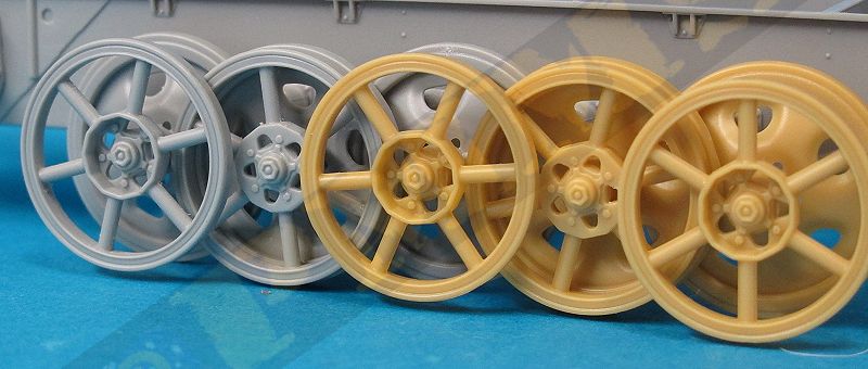
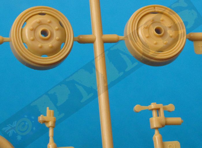
The road wheels have the solid dish type for the inner wheels and the 6 spoke type road wheels for the outer wheels which is the appropriate configuration as seen in some period photos. There is a bit of clean-up needed on the spoke wheels to eliminate the mould seam on the spokes and the inner rim face which does become a little tedious but anyone having experience putting together Panzer IV or Churchill road wheels or similar will find these a breeze.
As with the GWH kit the solid dish and spoke road wheel sizes are slightly different diameters, this is due to the design of the actual steel wheel which incorporates an internal rubber damped rim while the solid spoke wheel has the rubber section on the outside and the natural compression has all wheels with even track contact. This means both types of wheels included in the kit are technically correct but unfortunately due to the fact the wheels are in plastic there is no compression and this results in a scale issue with the assembled suspension when translated from real size to 1:35 scale in that the slightly smaller spoke wheels don’t make ground contact.
On the actual sWS with mixed road wheels the compression of the outer rubber section of the solid spoke wheel due to the weight of the vehicle would see both sitting flush on the track surface. So while the kit wheels are technically correct unfortunately allowances for this compression is not replicated in the plastic kit wheels and you still have the spoke wheels hovering above the track slightly as shown in the images due to the difference in diameter of the wheels.
The quickest remedy is to shave down the rubber section of the solid dish wheels to replicate the compression allowing them to sit flush on the track surface with the smaller diameter spoke wheels. The small discrepancies may not be an issue for some and the small difference may not be that noticeable with the tracks fitted?
both have the same dimensions and detail included.
Note the outer spoke wheels are slightly off the ground due to being a little smaller in diameter to the full dish wheels.
At the back are alternate 2 part idler wheels, the initial spoke type and the later solid dish type with references showing the spoke type are more commonly seen so check if you are building a particular vehicle as to the idler type used.
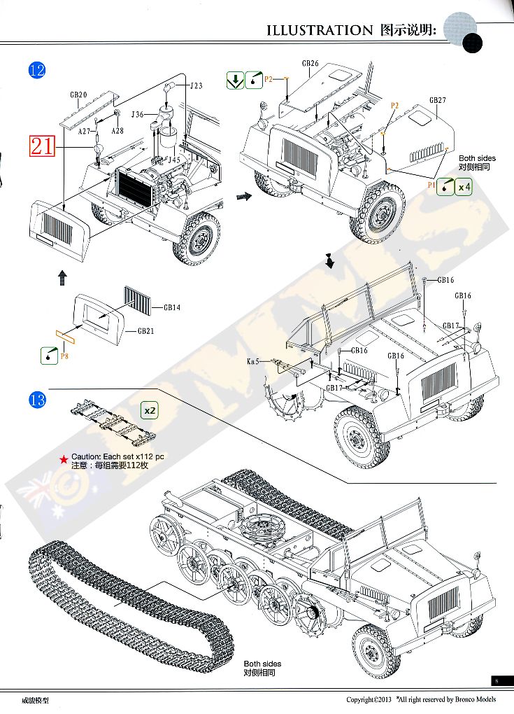
While the links are not workable they are large enough for you to drill and add a 5mm wire pin at each side to make them workable if you wished. Or if you have a set of Friul metal sWS tracks (set #ATL44) these should also fit as the Italeri sWS sprockets for which they are designed are the same size and tooth pitch as the sprockets in this kit.
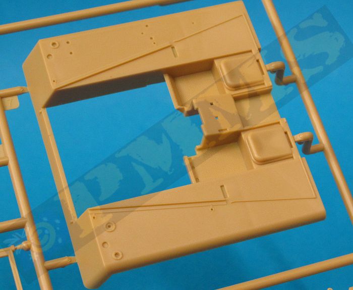
Added to the fenders are the pioneer tools with moulded on clips, the two front head lights with clear lenses and two part Notek light and the width indicator posts with a mirror on the left post.
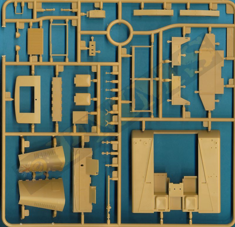
Under the left fender is a three part exhaust muffler with the end of the short pipe hollowed out for a better appearance and two bumper bars are added to the front.The fit of the upper armoured cab to the lower fenders is very good with small locating pins resulting in no filler or trimming being required BUT you do need to trim some plastic off the firewall for the engine to fit properly. You don’t need to trim much plastic and repeated test fitting and minor trimming will result in much smaller gaps appearing inside the crew compartment. The inner pedal plate (B46) acts to hide the gap in any case if you just cut away the bare minimum to allow the engine to fit, see images.
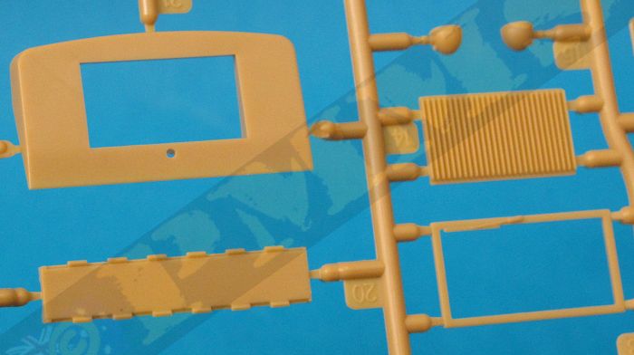
The front radiator coaming has an opening for the radiator which is a separate part added from inside with fine grill texturing as well as an etched number plate added to the lower front. The top hood panel fits between the front radiator panel and the firewall with all the panels fitted either side. The fit was good but there may be some minor trimming needed depending on the proper location of the radiator coaming and firewall.
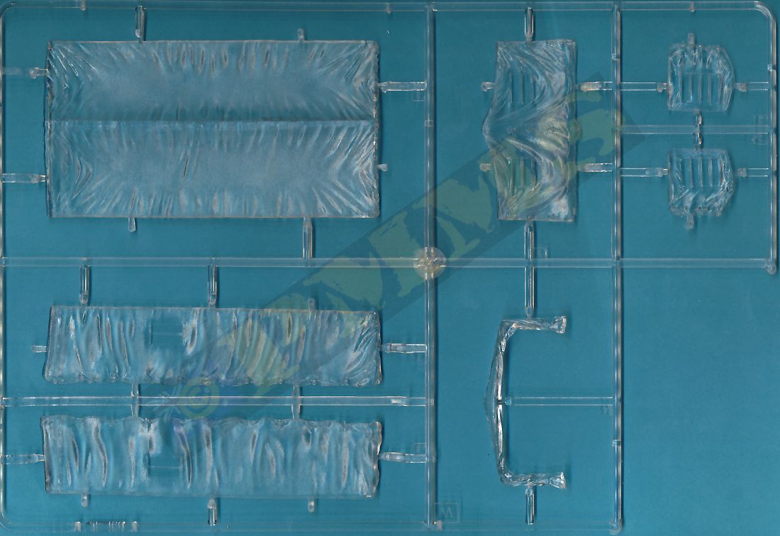
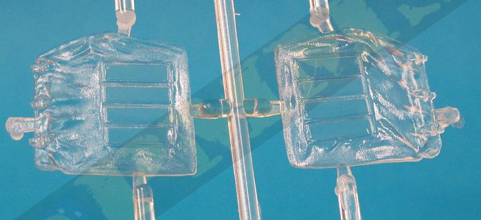
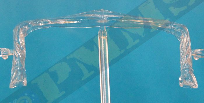
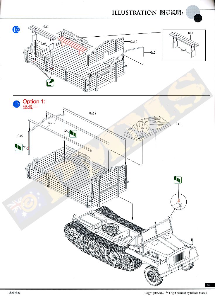
A separate canvas cover is supplied for the cap should you wish to add a roof as well as new side canvas doors in clear plastic that eliminates any join between the clear windows and canvas after painting, the texture on the doors is very well done plastic. If you fit the new doors it’s best to cut off the three moulded on tie down cleats on the side cab panels to allow for a better flush fit of the doors.
You should note that the rear support for the canvas roof is attached to the front of the rear cargo tray so you can't add the rood until after final assembly of the cab and tray.
The fit of the cab to the lower chassis is very good with small locating pins resulting in no filler or trimming being required.
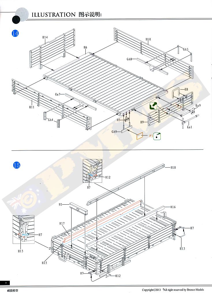
Added to the underside of the floor are long mounting beams for fitting to the lower chassis and there are locating recesses on the floor underside to make for a good alignment with the chassis frame.
Other smaller fittings to the cargo tray are the rear number plate bracket and tail light and two pioneer tools which have moulded on tool clips added to the real gate.
The fit of the assembled cargo tray to the lower chassis is spot on and trouble free and this allows you to paint the sub-assembly separate and add later in the final assembly.
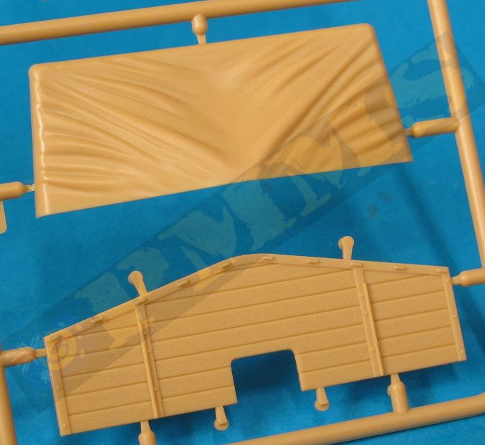
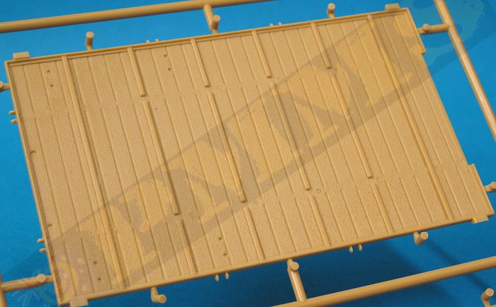
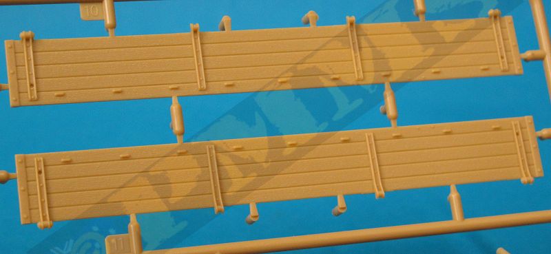
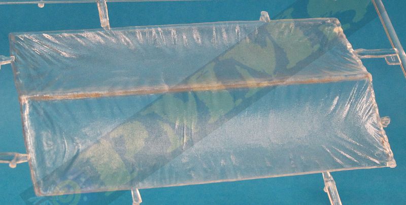
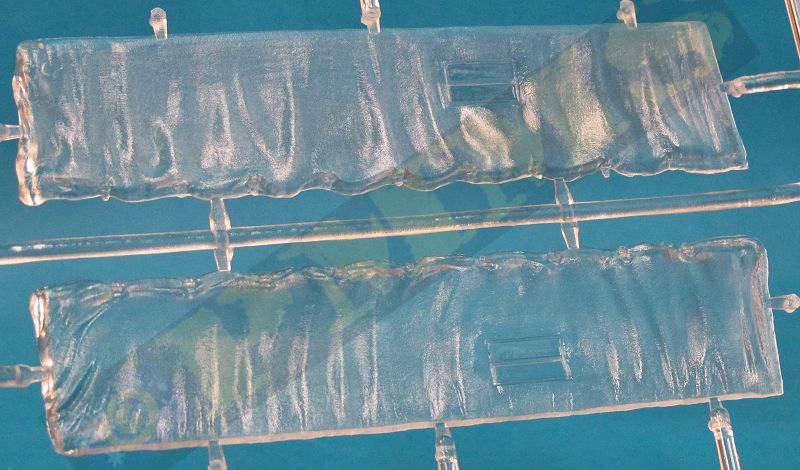
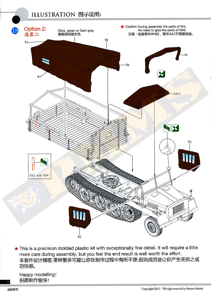
On the inside are two wooden bench seats with backrests also with nice wood grain free of pin marks plus the upper front wood panelling, rear and top supports for the canvas cover often seen fitted along with the new full canvas tilt cover supplied in clear plastic to allow blemish free window joins. The detail and texturing on the clear canvas is very well done although it’s hard to see before adding a primer paint coat to show this fully. The cover is in four main parts, the sides, rear and top sections with bevelled edges for a gap free join, but there are no locating pins so make sure the joins are aligned perfectly while glue as the clear plastic does make it harder to see the joins during assembly.
The assembled tilt cover is designed to fit over the plastic tilt frames but you need to trim some of the details from the sides of the tray as indicated in the instructions for the cover to fit properly. The fit is very snug indeed over the frames and carefully working this into place is the best option, I had one small issue in that the left rear corner join popped open and you will need to trim some plastic from the insides of the cover at this point to get a better fit. As this was the only corner to give any problems you may wish to simply fill any gap once the cover is in place to make things easier the choice is yours really.
The cover has excellent texturing and fabric details for a plastic cover and looks quite impressive when in place and fitting this means you don’t have to worry about the insides of the tray or adding a load as you can’t see inside apart from the small windows after painting.
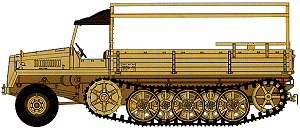
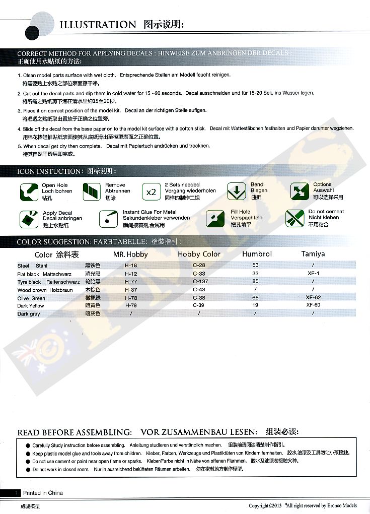
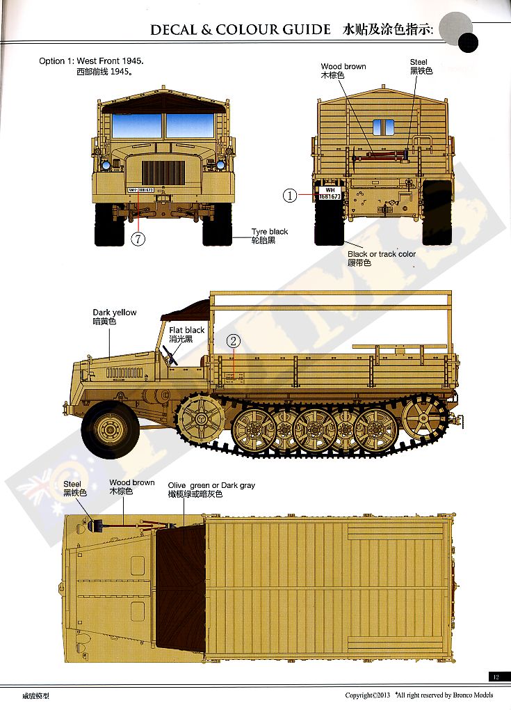
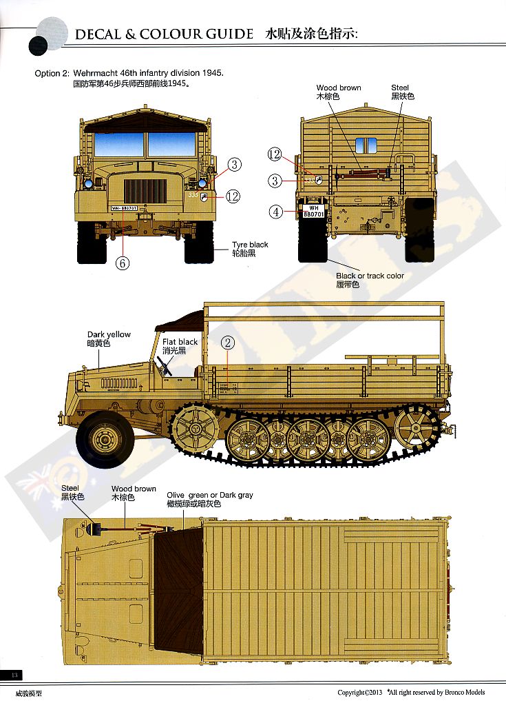
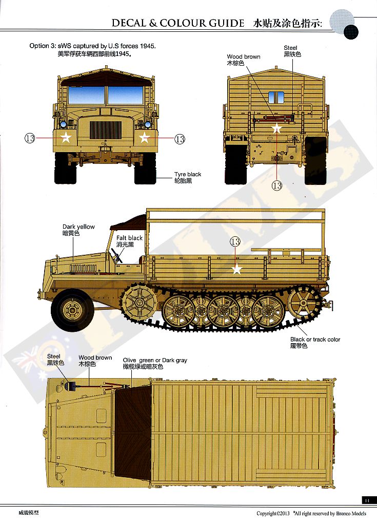
The small decal sheet is well printed in black & white with two WH number plates, two data blocks, unit insignia, 5 Allied stars and the instrument panel dials. The paint schemes provided are just three vehicles in overall dark yellow with two Wehrmacht vehicles and one sWS captured by U.S. Forces in 1945 which is in the standard paint scheme with the Allied Stars added.
| Option 1:
West Front 1945 Option 2: Wehrmacht 46th Infantry Division 1945 Option 3: sWS captured by US forces 1945 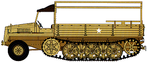  |
The inclusion of the full canvas tilt cover and front canvas doors is especially welcomed and these are very nicely textured and well done for plastic parts and add a distinctive appearance to the model over the basic open configuration.
Rating: 9/10.
Click on thumbnails for larger view

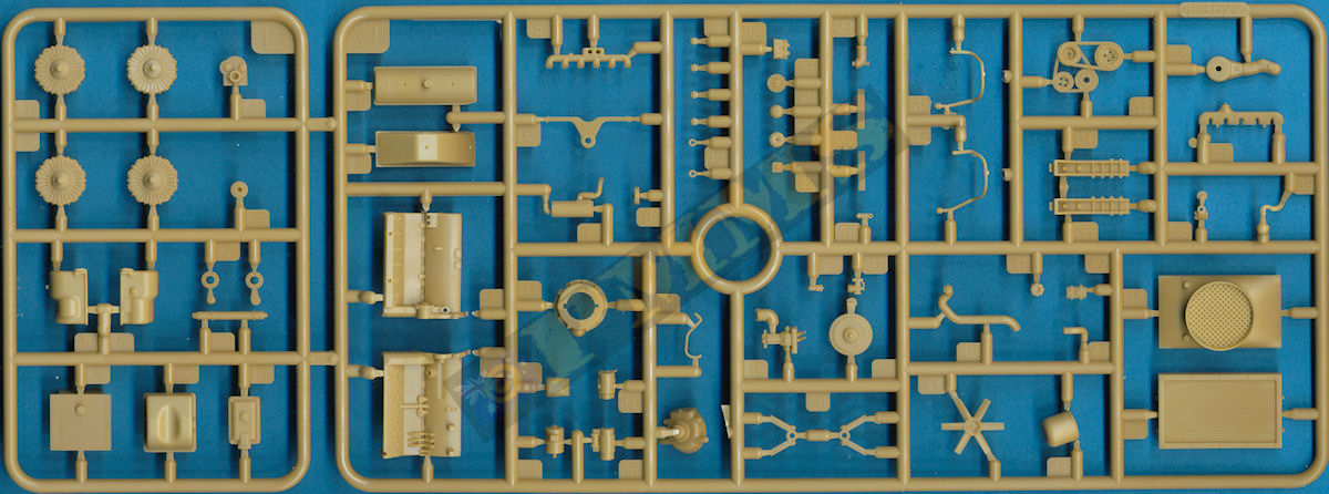
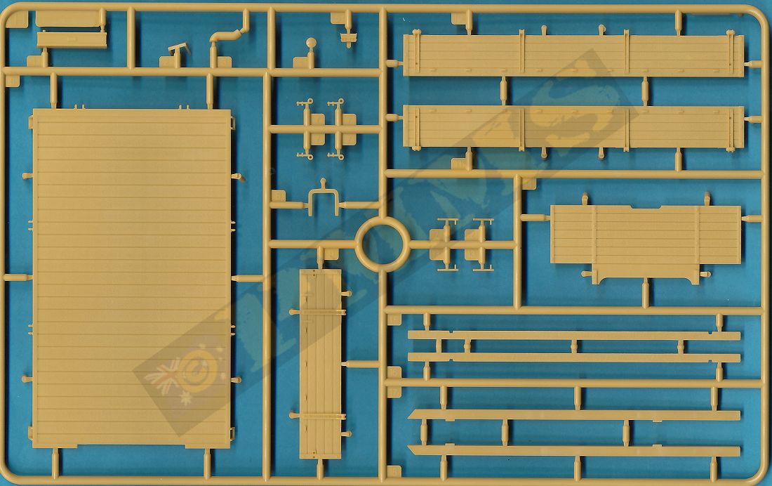
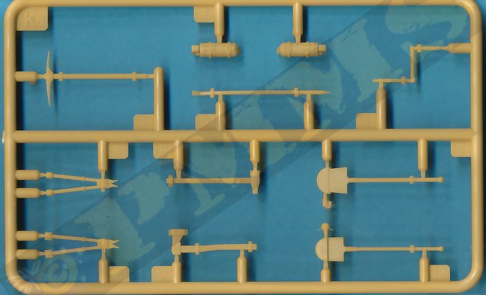

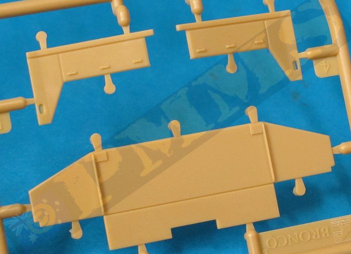
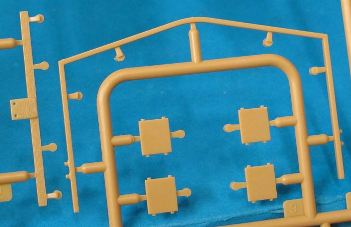
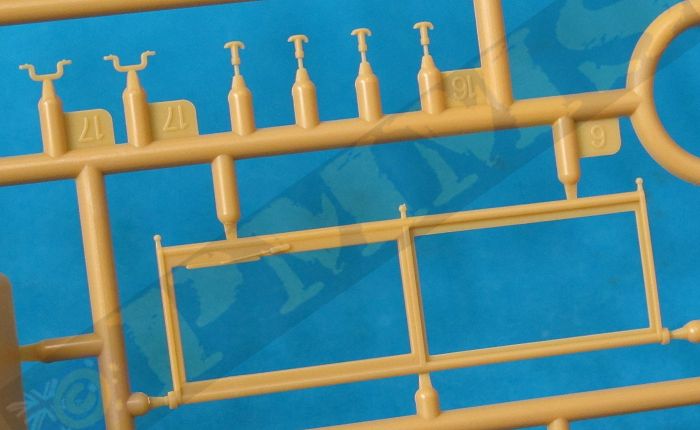
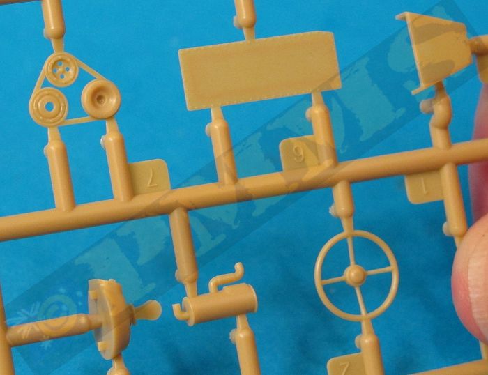
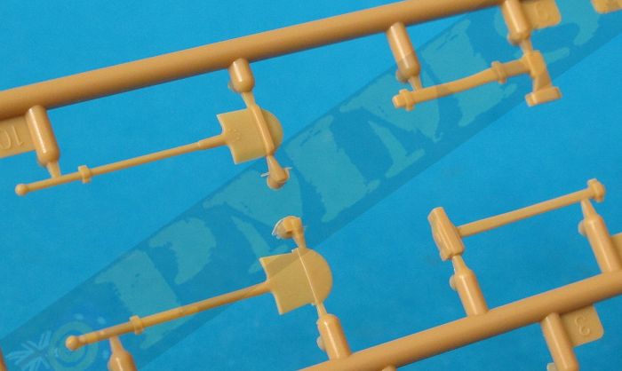
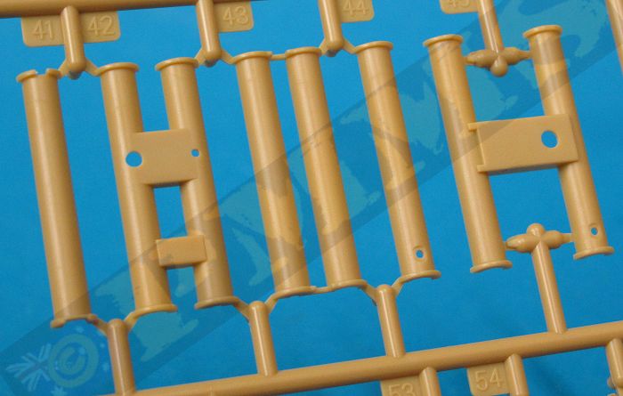
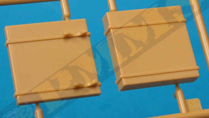
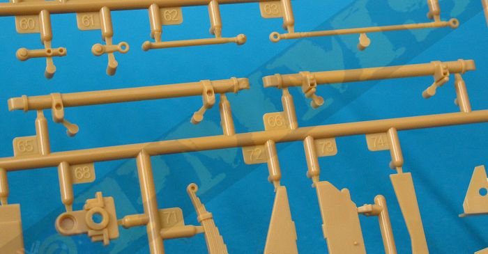
Sprue detail images


Instructions


| Büssing's schwerer Wehrmachtschlepper (sWS), armored and unarmored variants Nuts & Bolts Vol.41  |
mittlerer Zugkraftwagen 5t (Sd.Kfz.6)
and Schwerer Wehrmachtsschlepper Panzer Tracks No.22-3  |
Halftrack Vehicles of the German Army 1395-1945 Schiffer Military History ISBN: 0-88740-758-7  |
German Medium Half-Tracked Prime Movers 1934-1945 Schiffer Publications ISBN: 0-7643-0263-9  |
 for
the review kit.
for
the review kit. 