
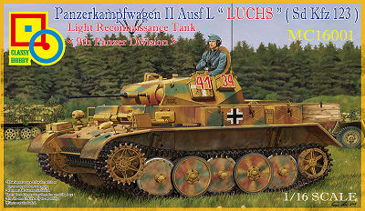
Panzerkampfwagen II Ausf L "Luchs" (Sd.Kfz123)
Light Reconnaissance Tank [9th Panzer Division]
Classy Hobby 1:16 Scale Kit No. MC16001
Review by Terry Ashley
Part 1 of 3
The kit contents:
674 parts in light grey plastic
12 parts in clear plastic
208 individual track links in light brown plastic
210 metal track pins
77 etched brass parts on 1 fret
1 x 200mm length of steel wire
1 decal sheet
1, 31 instruction booklet
1 colour painting guide sheet
Taking into account minor discrepancies for the manual measurements etc. all the measurements came out virtually spot on for 1:16 scale with only some minor differences, the largest difference was just 0.575mm so with the majority of parts measured being within a 0.5mm (plus or minus) tolerance we can safely say the kit is as close to 1:16 scale as you could get.
The kit is moulded in light grey styrene plastic apart from the individual track links in light brown plastic and clear parts, plus obviously the etched parts, the plastic is of medium hardness making it hard enough to include crisp details yet easy to work with when trimming the sprue attachments etc. and reducing the tendency to remove excess plastic while trimming.
On some of the longer thinner parts such as the tools, antenna and others the plastic was flexible to a degree which can be advantages in reducing breakage but a couple of the very thin parts such as inner turret wiring (part G40) did had a couple of breaks, these are best identified and re-glued while the part is on the sprue to reduce problems after. While finer parts are slightly flexible the major parts are hard enough and free of any warping as with most current kits. For general clean-up work I used the #11 blade scraping method to remove most of the mould lines with a final light sanding if need be? On the odd occasion the surface roughed up a little with scraping (mostly in tight corners or curves) I simple reduced the pressure and changed the blade direction to rectify the problem but overall there were few issues and everything went as normal. A quick tip while scraping with the #11 blade, I always hold the blade at an angle in relation to the part and use light pressure, this tends to alleviate any issue with this or any other kit for that matter, this method also helps when scraping a seam or mould line on a circular part as it tends to help retain the curve so you don’t get a “flat spot”.
The standard of moulding is good overall with some clean crisp detail, most notably the larger bolt heads on the drive sprockets and other parts having excellent definition. Some very fine detail is included with fine embossed data on each track link face and the stylized “Bosch” embossed on the blackout headlight covers, the details on the inside and outside of the turret hatches is well done as is the inner visor mountings for the turret and front of the fighting compartment casemate with the outer visor covers able to be positioned open or closed. The latch details on some of the storage boxes is augmented with etched parts as are the separate tool clasps for good definition.
Conversely there is some more basic detail that could do with some enhancement; the welds are nicely depicted in places although some others may need re-doing with epoxy putty or similar for a better appearance such as the front and rear of the side hull joins and on the turret and others added that are not present on the kit. Also there is some degree of fine flash on many of the larger and smaller parts (some very fine, some more prominent) while some of the smaller parts have locating pins that don’t quite fit into the locating holes requiring drilling the holes larger (while others were ok), a few had a locating pin on the instruction illustration but the part did not and all this means you should definitely test fit parts before gluing to assure you get the best fit.
There are also a few indented pins marks to be filled on a few parts and some raised pin marks more easily trimmed smooth while others are in positions not seen after assembly so you can forget these. All of this along with the quite pronounced mould lines on many parts, especially the smaller parts results in a fair bit of clean-up needed before assembly.
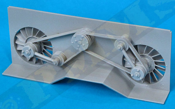
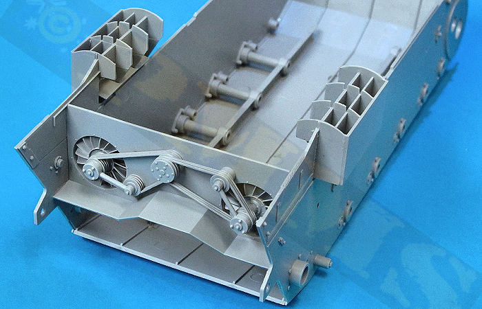
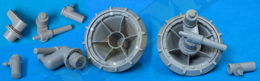
Assembly was straightforward but I did need to slightly shorten the locating pins through the fan belts when fitted to allow the end connectors and plate (parts D13, H32) to sit correctly but test fitting will determine if this is needed. Obviously this assembly will need painting before fitting into the hull but as it’s not that visible through the top grills and issues with the clean-up will be difficult to see in any case.
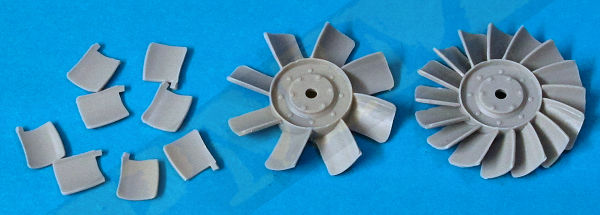
Assembled Cooling fan and bulkhead
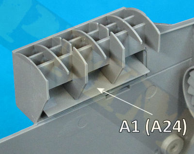
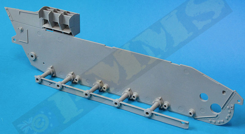
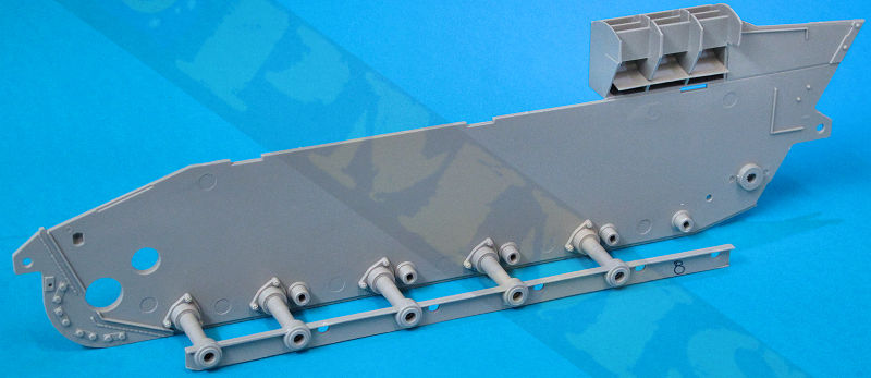
Each separate hull side plate comes with the large intake boxes already moulded on, the kit correctly has the left side intake box shorter than the right side box and there are lower plates (parts A1, A24) fitted into the intake boxes to blank these off, this is also the intake channel on the actual intakes. These plates are a little fiddley to fit and once in place the lower edge protrudes out from the hull wall, the instruction show it level with the hull wall but this protrusion is not a problem as they do no interact with anything after assembly so you can leave them as is.
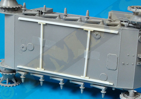
Also added to the hull walls are the torsion bar supports (parts Bd6) and long support beams (parts F7, F8), the supports fit to the hull without problems and when fitting the beams they need to be pressed over the supports as tightly as they will go as these need to fit into channels on the hull floor. It’s best not to glue the beams into place until the lower hull assembly so you can check that the beams sit into the lower hull channels correctly. Mine did perfectly with the beams pushed as far as will go over the supports.
The instructions show to fit the small lifting hooks to the hull sides at this stage but it may be better to leave these off until after the hull is fully assembled to avoid damage, which is up to the individual of course.
The same goes for the spare track rack fitted to the front of the lower hull (in step 4), this rack is made up of some delicate parts and again is best left off until after the lower hull is fully assembled.
The two hull side walls with torsion bar supports can now be glued to the lower hull plate, as mentioned first test fit to ensure the torsion bar support beams fit perfectly into the lower hull channels; with this ok you can then attach the side walls to the hull floor. The fit here is very good and precise with the torsion bar support beams helping to align and ensure the walls are perfectly square with the floor plate.
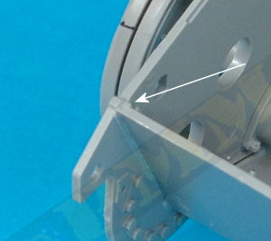
The only fit issue was with the up-curved front hull section, the right side fitted perfectly snug into the weld channel on the side plate but there was a bit of movement possible with the left side weld being moulded slightly forward of the right weld position. This means you must ensure the top of the left side of the floor plate is glued perfectly aligned with the small raised notch on the side wall, if not you can have a small gap between the front plate and glacis later when the glacis if fitted. See image.
With the lower hull assembled the rear fan/pulley assembly bulkhead can be fitted into the hull, the bottom corners fit into the locating ridges on the hull walls but you need to ensure the bulkhead sits perfectly vertical as there is no locating tabs at the top of the bulkhead but this shouldn’t be a problem.
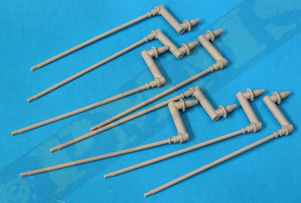
Note the 1st and 5th swing arms (parts D40, D42) have small brackets (parts D39, D44) added for fitting to the shock absorbers later and these swing arms fit at opposite ends on the hull on either side, as clearly shown in the instructions
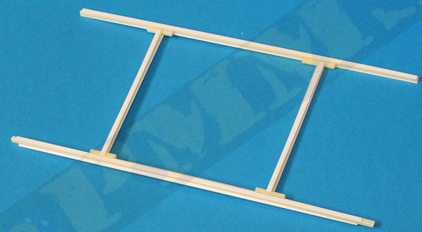
To align the bars at the correct ride height I used the plans in the Panzer Tracts book to determine this height and made a spacer jig frame from plastic strip to sit on the hull bottom while the glue on the bars dried completely. The strip on the jig is 2.85mm in height and you should make sure this sits evenly on the hull bottom missing the raised access panels so the hull is even, you then sit the hull (with spacer jig) on a flat surface (a piece of board or similar) with the axles all sitting touching the board, this ensures they are all at the perfect height, when the glue has dried completely you can remove the jig and assemble the rest of the running gear. See images
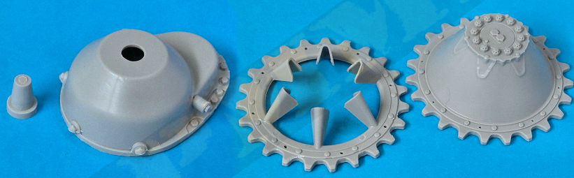
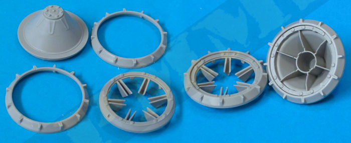
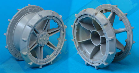
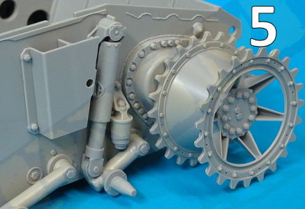
The drive sprockets are the correct diameter with the correct number of drive teeth (23) and are in two halves, the inner solid sprocket disc that has well done bolt head details on both sides of the disc. The outer disc has the six concave spokes and again well done outer rim bolt heads on both sides. The central hub has excellent bolt head detail definition with the correct number of bolts. The only clean-up needed is some fine flash around the base of the spokes with the outer disc attaching to the inner disc by gluing the spokes to the raised locating ridges around the disc. You need to ensure the drive teeth on both discs align as there is no actual locating pin and due to the 23 drive teeth and six spokes the drive teeth don’t align in some positions, you just need to rotate the outer spoke disc until the drive teeth on both sprocket discs align properly, no big problem.
The drive sprocket attaches to the final drive housing by way of a single join pin (part D54) and if you want the sprockets to be movable you have to glue the pin through the final drive to the sprocket without getting glue on the final drive housing, not an easy task. This is best done by putting a dab of thicker tube cement on the end of the pin and fit this through the final drive hole into the sprocket but inevitably glue will come into contact with the final drive as there is almost zero clearance between the pin and final drive. To make sure the sprocket still rotates hold the sprocket hub and pin tightly between your thumb and forefinger and rotate the final drive until the glue ‘goes off’ and loses its grip to allow the sprocket to rotate feely, it is best to have the sprocket movable as this helps when fitting the track later.
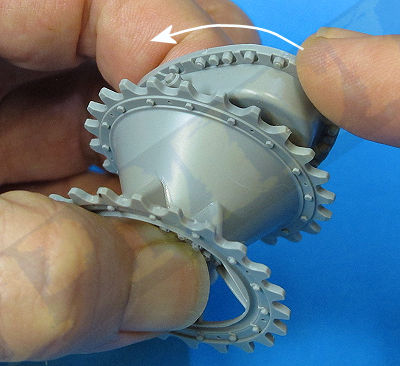
Note: The fit of the drive sprocket to the final drive is a little loose and it can move about a little laterally, to remedy this you can simply cut a small amount off the end of the securing pin (part D54) allowing the sprocket to fit tighter, but in any case the tracks when fitted will hold the sprocket square, so you can leave as is, trim the pin or glue the sprocket in place whichever you prefer but as mentioned having it movable does help when fitting the tracks later.
The final drive/sprocket assemblies fit without any problems to the raised housing base on the hull sides and makes for a very robust join due to the large contact area; the base also has nice welds around the edges for a good appearance.
Also on the back of the inner disc rim there are some indented pin marks that are visible after assembly so you should fill these and sand smooth before adding the outer segment ring taking care not to damage the bolt head detail around the rim.
The outer idler swing arm (part D28) has the idler mounting ring (part D30) held in place by the cap (part D12) and if you want the idler to rotate no glue should get onto the mounting ring as you assemble the parts. For a snug fit you should trim a little from the end of the pin on the swing arm to allow the cap to hold the mounting ring snugly in place otherwise there is a little lateral movement. If you don’t want the idler to rotate just glue all the parts together and move on.
The inner swing arms (part D57, F10) has a small pin fitted through it that holds the track tensioner piston (parts G22, G52) in place and again if you want the tensioner to be movable make sure not to glue the pin to parts D57, F10. With the tensioner piston attached glue the two swing arm sub-assemblies together (B + F10, B + D57).
the excess flash has been trimmed from the inner disc ribs ready for fitting.
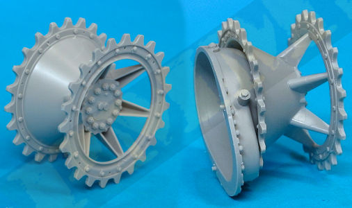
Note the idlers are fully assembled here to show the details
but you shouldn't fit the outer sprocket half until after the road wheels have been added to avoid any fit issues
with the inter-meshing of the wheels and idler.
When fitting the idler swing arms to the hull there is a small notch on the swing arm neck (parts F10, D57) that fits into the hull mounting hole, inside this hole is three notches that allow you fit the swing arm at different angles, simply choose you desired swing arm position and secure the swing arm in place. Choosing the middle notch will have the idler arm in the ‘neutral position’ but the choice is yours.
As you fit the swing arm/tensioner piston assembly to the hull you fit at the same time the tensioner cylinder (parts D27) and this has a small clip pin that fits into the corresponding hole in the hull sides, I had to slightly enlarge this hole to allow the clip pin to fit through.
A quick note here to check the part numbers in Step 27 to make sure that the tensioner cylinder is numbered as D27, this was originally shown as G22 but may have been corrected before the kits release, if still shown as G22 it should be D27.
With the swing arm/track tensioner assemblies fitted you can attach the inner idler disc sub-assemblies with the mounting (parts D30) fitting to the ribs on the back of the inner idler disc, the fit here was good after cleaning up the excess flash as mentioned above.
The bump stops (parts Bd20) have an additional bolt head (parts Bd25) added for good detail and the stop glued in the positions indicated on the hull sides (1). The large shock absorber guards (parts Bd36) can be glued in place (2), note the guards cover the tops of the bump stops on the left side but not on the right side. The top cylinder (parts Bd38) can be added and secured in place with the securing bracket (Bd12) as mentioned above leaving the cylinder free to move (3).
Lastly the shock absorber piston in slipped into the cylinder and clipped over the brackets attached to the swing arms to finish off the assemblies (4), there were no fit problems here and only the mould lines to be cleaned from the parts before assembly.
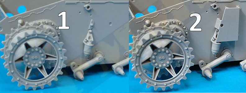
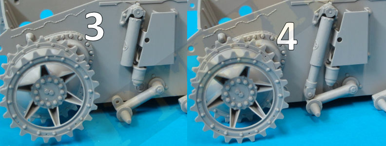
Image of right side showing different suspension part location.
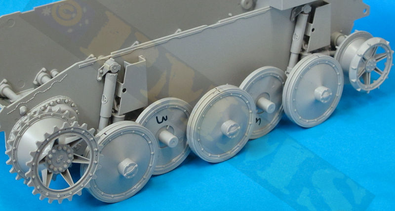
Views of the 5th axle suspension.

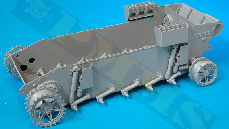
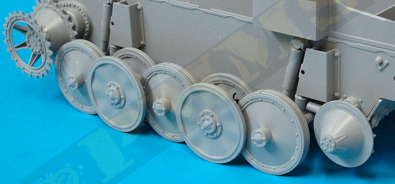
Overall view of the running gear with axles glued in the neutral position as described above.
The wavy contours of the outer wheels is nicely done and appears to represent this feature nicely, the hub bolt ring and covers are also nicely detailed giving the wheels an overall nice appearance.
Once again if you don’t want the wheels to rotate after assembly you can firmly glue these onto the axle stubs as you go, if to be movable you fit the inner wheels (parts Bd3, Bd4) to the axle stubs and secure in place with securing caps (Bd7). You should still use these securing caps if gluing the wheels solid as they help to keep the wheels aligned correctly. Note at this stage I glued the central mounting hubs for the outer wheels (parts Bd13, Bd15) together and glued these hubs to the back of the outer road wheels (Bd1) ready to be fitted later.
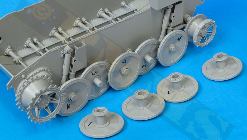
Next attach the middle road wheels (Bd6) directly to the inner wheels (Bd4) making sure to align the locating pins and then attach the hub caps (Bd5)
Finally attach the outer road wheels (Bd1) with mounting hubs already attached to the inner road wheels and you are done with the wheels, all quite straightforward without any issues arising.
to Review Part 2 ![]()
to Review Part 3 - Conclusion and Sprue images ![]()
Please to help the reviews continue, thank you
