
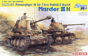
Sd.Kfz.138 Panzerjäger 38 für 7.5cm PaK40/3 Ausf.H
Marder III H
Dragon 1:35 Kit No. 6331
Review by Terry Ashley
The prototype Marder H was built on the 38(t) Ausf.G chassis with the production vehicles based on the updated 38(t) Ausf.H chassis with a number of detail updates, hence the designation Marder III Ausf.H.
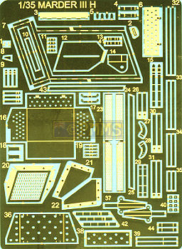
This consists of 380 parts in light grey plastic, 7 in clear plastic, a bag of individual track links plus a large etched fret including an etched rear basket and metal 75mm barrel and of course the instruction sheet and two small decal sheets.
The kit includes a full interior for the lower hull and fighting compartment as well as the 7.5cm PaK40 taken from their previous kits #6249, #6250
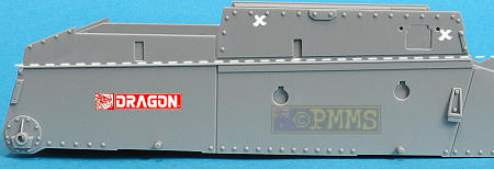
Hull:
The lower hull tub has the floor and both sides moulded together with well
defined detail on both sides of the hull walls for the inner fighting compartment
and insides of the final drives and includes revised upper edges but the
top row of bolts is incorrect for the Marder III H.
The position of the right side vision port is incorrect and this should be 2mm further back which is easy enough to do but you will have to fill part of the port opening and the front locating hole in the process.
Detail on the tub exterior is very good with rivet detail on the bottom and sides as well as the idler mountings included with separate final drive covers and return roller mountings.
The separate front plate is in two parts to not compromise the detail on the upper and lower sections with the fit very good as is the separate tow hooks but you should not attach this plate to the hull until the interior is done or there may be problems fitting the transmission/gearbox if you do attach the front plate now.
There are a couple of detail issues with the tow hook brackets having a rounded top profile but this should be square and the top and bottom row of rivets should be lower than depicted but there is little you can do about this?
On the inside are two part final drive fittings and front brackets which fit snugly to the inner side walls with the transmission/gearbox having crisp details included for all the basic detail including the cooling ribs on the gearbox and textured drive shaft cover. The driver’s controls are in one piece and fairly basic and there is no driver’s foot pedals or Driver's instruments included with three part seats but the mountings are again very basic plus the distinctive wooded mat for the lower floor is included and added to the left wall are the two 5 round racks (total 10) with additional etched parts. There should also be two additional 8 round ammo racks at the rear of the lower compartment but while these are included on sprue G for some strange reason the instructions show not to use the parts?
The ammo tubes have commendably thin edges but the tops lack the correct profile of the rear tudes and you may want to trim thes e for a more accurate shape?
Once the transmission/gearbox is assembled this should be fitted inside the hull and you will have to flex out the front sidewalls slightly to insert the pins on the drive shafts (parts D46) into the final drive fittings (parts D55/56) and this is the reason for leaving the front plate separate as you won’t be able to flex the sidewalls to fit the transmission with the front plate in place.
The rear firewall and drive shaft fit neatly in place but the firewall detail is not correct for the Marder III while the front seats and the front plate can be fitted but again you may have to flex out the side walls slightly to get this in place. The fit is good with the glacis also fitting neatly in place with the transmission visible through the separate inspection hatch and of course it’s best to paint the interior before adding the glacis and superstructure.
The separate glacis inspection hatch fits neatly into place without any problems and added to the glacis is the Notek light which has an etched part for the light face and the mounting bracket for added detail.
The separate Driver’s plate has additional separate parts for the two visor covers and round machine gun ring but there are a number of detail issues with this plate as a result of using the Ausf.G plate and not a revised Marder III type plate.
Firstly the circular machine gun ring is about 1mm too far to the left and slightly too low as well as the six bolts in the incorrect position, its simple enough to cut off the inner locating ridge and rotate the ring to locate the bolts to the correct position as well as relocating the ring on the front plate. This will mean altering the cut-out for the machine gun but this shouldn’t be too much trouble while the machine gun barrel has the cooling ridges the same width for the full length of the barrel but they should be wider for the portion of the barrel inside the cradle but this may not be that noticeable?
The left side visor should also be positioned closer to the MG ring meaning the visor should actually be 1.5mm further to the right. As a result to the visor being too far to the left there is no room for the centre bolt on the left of the plate which is missing and will have to be added after relocating the MG ring and visor, there should be three left side bolts on the front panel for the Marder III as opposed to just two on the Ausf.G.
If you relocate the visor the inner opening will have to be partially filled as this is exposed after the port is moved and a little work will be needed here and again some may not bother with any of this if true accuracy is not a real issue?
On the inside of the driver's plate are additional clear periscope parts, the full MG body with a nice ammo belt that you can bent to shape for better effect as well as small etched parts to hole the front visors open if you wish.
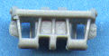
Added to the small upper hull plate in front of the gun mount (part G23) is the large barrel travel lock but again there are a couple of detail issues with this.
There are six bolts on the main hull bracket but there should only be four and it’s simply to cut off the centre two bolts to address this. At the front of the lock mounting bracket there should be a 2mm space between the bracket and the bottom of the travel lock (part G32) but this sits almost flush with the bracket and the side supports lack any real detail with this whole assembly being rather simplified but the lock is movable after assembly allowing it to be positioned as required.
Added to the hull sides are the separate fenders which are moulded commendably thin with rib embossing raised on the top but the ribs at the front of the left fender are not correct and should mirror that of the right fender while the ribs are indented underneath for some of the nicest plastic fenders that probably negate the need for etched replacements. The fender support brackets are all separate parts and also moulded nice and thin with a channel embossed along the hull side to locate the fenders.
There is an issue here as the 38(t) fenders have a distinct upward kink half way along the fender length with the kit fenders mounded perfectly straight. Included with the kit is a jig on sprue B for the kink contour with the instructions indicating you should bend the fenders using this jig as a guide?
Unfortunately the locating channel along the hull side is also perfectly straight and does not allow for the kinked fenders meaning if you do add the fender kink the fenders will not fit into the channel and the front of the fender will not mate to the top of the glacis/final drive housing as this is where the straight fender meets. So there is a fair bit of work involved altering the locating channel and other angles to incorporate the kink or just live with straight fenders.
Other items added to the fenders are the typical perforated 38(t) storage box which is provided in both plastic and etched metal depending on your preference. All the tools are moulded nicely without attachment clips which are provided on the etched fret to add a nice detail touch.
At the back is the separate rear plate which has the central round inspection hatch as a separate part and other smaller fittings including early and late style idler mounting brackets. Care is needed when fitting the rear plate as the rear hull tub sidewalls are bowed inward slightly at the top and careful coaxing was needed to fit the panel which straightens the hull walls in the process.
There is a notable detail omission on the rear plate as the Marder III H had a small port added to the bottom right next to the tow hook with a diamond shaped cover but this is completely missing and you will have to add this from thin card.
You should also note the instructions indicate to put the tow hooks on the wrong sides and part B24 and B25 should be transposed with the pig tail hook pointing outward on both sides, not inwards as indicated.
Added to the rear plate is the three part exhaust with separate outlet cover but the exhaust is 1.5mm too narrow when compared to the Panzer Tracts No.7-2 plans.
Suspension:
Each suspension bogie is made up of the hull mounting, two separate swing arms
and the leaf spring unit with the swing arms attached with a face plug that
allows the arms to move but the springs are glued in place so these is only
downward movement possible for the wheels after assembly. The fine mould
lines on the springs are easy to remove with the bogie units fitting together
as you attach to the hull side as the spring locating pin is on the hull
side and also used to locate the bogie mounting plate.
The wheels are the correct size and have the correct number of rim bolts on both sides of the wheels and these simply glue to the axle stubs on the swing arms while the two part drive sprockets (with separate hub cap) and idlers wheels also have detail on both sides of the wheel discs. Two styles of drive sprockets is provided, those with and without the eight outer lightening holes to use as required while the idlers have the teardrop shaped lightening holes included these are undersized when compared to the rear idler and it would be difficult to enlarge these.
The return rollers have nice hub detail as well as the “continentau” embossing on the side wall but it’s a little oversized if you want to get real picky but will look good when painted and weathered to highlight the embossing, and it’s easy to convert the ‘u’ to an ‘l’ if you want to do this.
Tracks:
These are provided as individually moulded “magic tracks” which
have nice detail including minute casting numbers on the edge of each link
with no cleanup required.
The tracks are designed to be glued together and are not workable and you will
have to incorporate the track sag as you glue the lengths together. By gluing
a length together and letting the glue “go off” you can them add
it to the suspension and add the curve around the drive sprockets and idlers
as well as the track say easier.
The assembled track runs look very good but if you prefer workable track links which take care of the track sag themselves then those from WWII Productions would be a simple alternative.
Engine Deck:
At the rear is the separate engine deck redesigned for the Marder III with separate
side engine access doors as well as separate rear intake grill section with
the engine deck having nice details including the nicely represented hex bolts.
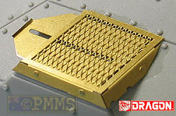
The grills located under the lip of the engine access doors is provided as etched parts and these have been revised to better represent the actual grills but they are still located on the outside of the doors when they should be located in a recess on the inside of the door lip.

The separate small intake grill has a finely etched mesh screen cover provided as well as the sliding cover that requires the sides of the frame to be bent to shape which is quite easy using a good bending tool, I used the original Etch Mate for the job without any problems. One thing to watch is when you bend the side with the opening for the sliding cover to ensure you make the bend so the slot is fully open and not bent half way into the opening but if careful the door will easily slide open and closed after assembly. Even so I did have to reduce the width of the cover slightly to allow it to fit through the opeing in the etched frame and you test fit to see what filing is needed if any? A very small etched wing nut is also provided which holds the sliding cover at the required position and this will need care when attaching.
The new deck includes the centrally located gun cradle travel lock but this is located about 1mm too far forward and is a little undersized as well as the bolt spacings on the centre panel being incorrect and the location of the forward engine door hinges are in the wrong location being 1.5mm too far back. All this might not sound a lot and could be hidden once the gun is fitted but you may want to alter these for true accuracy.
The two side “trays” are the correct size with the right perforation spacings but the forward locating “leg” is designed to fit the incorrectly placed hatch hinges so if you correct these you will have to modify the tray leg as well, but again this is only minor and attached on the bulkhead just in front of these trays are the two gunners seats (parts G54) but these are just plain plastic without any detail at all and are also positioned too far outboard and you should move them inboard level with the hull side plates.
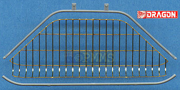
At the back is the metal basket which is made from thin round rod on the rear Marder III but the kit provides this as flat 2D etched metal with thin plastic outer edges added. This 2 dimensional PE simply doesn’t represent the real round rod at all well with the rear upward curve being too sharp and fitting the plastic edges will prove to be an interesting proposition. It’s best to use thicker cyanoacrylate for this and try and hold the plastic in place long enough for the cyanoacrylate to bite without gluing you fingers as well with the rear part also requiring slight bends added to the etched basket to conform to the plastic outer frame and care will be needed with this.
From a distance the etched basket could look okay but close inspection shows the limitations of providing 2D etched metal for such a part but there is little you can do other than scratch a new one from thin wire with additional etched supports provided for both the side and rear platforms.
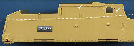
Superstructure:
The superstructure sides are moulded in one piece per side which makes assembly
easy as there isn’t any but the detail on the inside is quite basic
with a few pin marks to contend with but these shouldn’t be a problem
as there isn’t much detail around them while being removed.
On top is the separate roof but compared to the Panzer Tracts plans this is about 1mm too narrow each side making the contours a little off and the two periscope openings are 2mm too far inboard and would have to be moved outward for a more accurate configuration.
Added to the inside of the superstructure wall are the fold down side periscopes, radio on the right side and the ready round magazines as well as the periscopes on the inside of the roof while on the outside is an multi-part etched rack and cam net support posts.
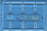
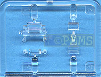
The 7.5cm gun comes from the previous PaK40 kit #6250 and you have a choice of aluminium or plastic barrel depending on your preference and a choice of the three different style of muzzle brake with all three styles seen in photos of Marder III Hs so you can take your pick or refer to photos if they exist of the vehicle you are building.
The muzzle brakes are in one piece for the main muzzle brake using slid moulds and have separate end fillets with internal flanges. The rear breech block is very detailed with the breech made up of four main parts with a separate movable breech block of three parts plus breech opening handle, side piston and lower support for a very detailed barrel assembly.
The gun cradle is in the usual two halves for this type of gun and is the correct length with the rest of the gun cradle being nicely detailed with many separate parts and alternate front cradle panel, separate side trunnion supports, two part recoil cylinders, traverse hand wheels and smaller fittings for a very busy assembly.
The main curved gun shield is in one piece which fits to the front of the gun mounting and between the two superstructure sides with the whole gun sitting on the large T gun mounting that fits between the hull sides.
As a bonus there is a selection of 7.5cm ammo boxes, round canisters and 7.5cm rounds and empty shell casings to use in diorama settings
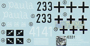
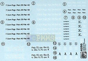
Decals:
There are two small decal sheets, one from the PaK40 kit with a selection of
stencilling and a new sheet with markings for 4 vehicles. You should note
if modelling
"paula" that the lower front plate does not have the additional
raised detail included on the Dragon kit part but has the
smooth front plate.
| Pz.Jg.Abt.171, 17.Inf.Div, Italy 1943 |
2./Pz.Jg.Abt.39, 21 Pz.Div., Tunisia 1943 |
23.Pz.Div., Eastern Front 1944 "paula" |
Unidentified Unit, Italy 1944 |
Conclusion:
Overall the kit is cleanly moulded with the details present well defined
and will assembly quite easily for a nice representation of the Marder III
H but there are a considerable number of detail and dimensional issues
if you are concerned with accuracy but if not just build it and be happy.
Unless of course you want to build the prototype Marder III H on the Ausf.G chassis as the front and rear plates and other details will match this better than a production Marder III H.
Recommended 7.5/10 but with reservations on the number of detail issues for a production Marder III H.
All the issues mentioned above will be analysed in detail with the comparison review with the Italeri and Tristar Marder III H kits to be posted shortly.
The Sprues: Click on thumbnails for larger view


Close new window to return to review
See the 38(t) Subject Page for additional reviews of 38(t) related kits and accessories.
Also see the Comparison Review of the Dragon, Italeri and Tristar Marder III H kits.
References:| Panzerjaeger Panzer Tracts No.7-2 ISBN 0-9744862-9-9  |
Marder III Ausf.H Nuts & Bolts Vol.18 128 pages, Soft Cover  |
Marder III/Grille Wydawnictwo Militaria No.175 ISBN: 83-7219-025-9  |
| Marder III AFV Super Detail Photo Vol.4 Published by Model Art Co.Ltd.  |
Pz.Kpfw
38(t)Ausf.A-D in detail Special Museum Line No.38 Wings & Wheels Publications ISBN 80-86416-58-5  |
Ground Power
Magazine #100 - 9/2002 GALILEO Publishing Co.,Ltd. Japan  |
Page created April 2, 2007