
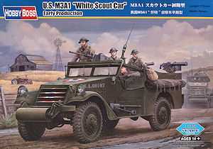
U.S.M3A1 White Scout Car Early Production
Hobby Boss 1:35th Scale Kit No. 82451
Review by Terry Ashley
It was powered by a Hercules JXD, 320 cu in (5200cc) inline 6-cylinder gasoline engine producing 110 hp (82 kW) with 4 wheel drive for a top speed of 55mph (89km/h) and was protected by 6-13mm face hardened armour plates.
The crew consisted of a Driver and up to seven others with six seats in the rear compartment and mountings for an M2 cal.50 HBMG and two M1917A1 or M1919A4 cal.30 MGs on a skate rail around the inside of the rear compartment.
The M3A1 was also supplied via lend-lease to allies such as Britain and Commonwealth countries as well as the Soviet Union, Belgian, Czechoslovak, Polish and Free French Forces.
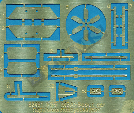
Note the later jerry can racks are included on the etched fret but these are not used with this kit, it does indicate we will see the late production SC soon from Hobby Boss.
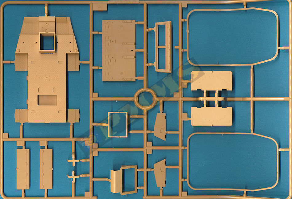
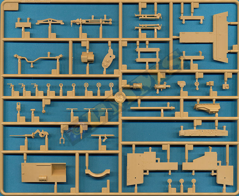
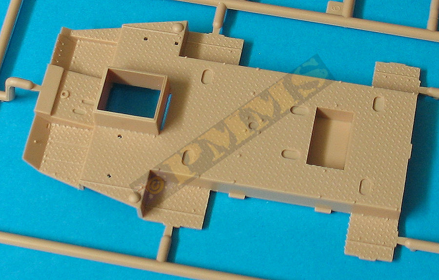
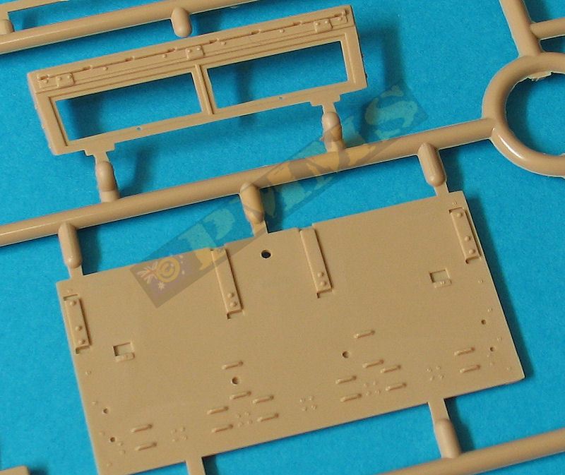
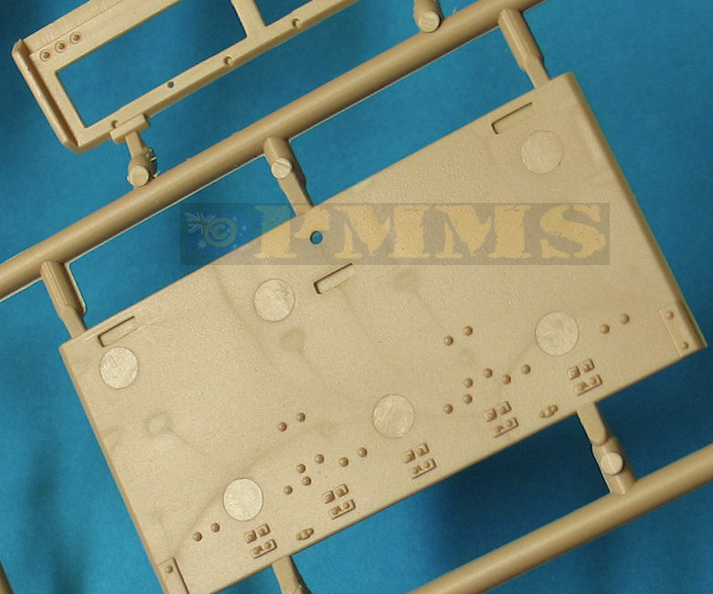
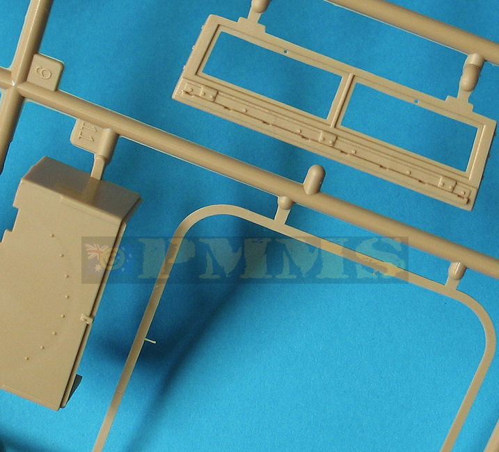
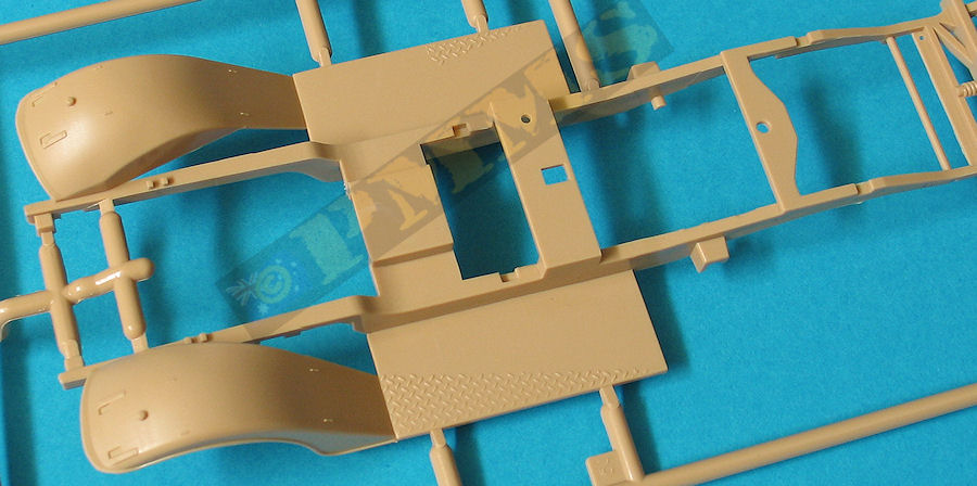
The standard of moulding is good with very little flash and just a bare minimum of pin marks, the most notable being on the inside of the driver’s compartment bulkhead and rear plate where there are some quite large pin marks to be removed.
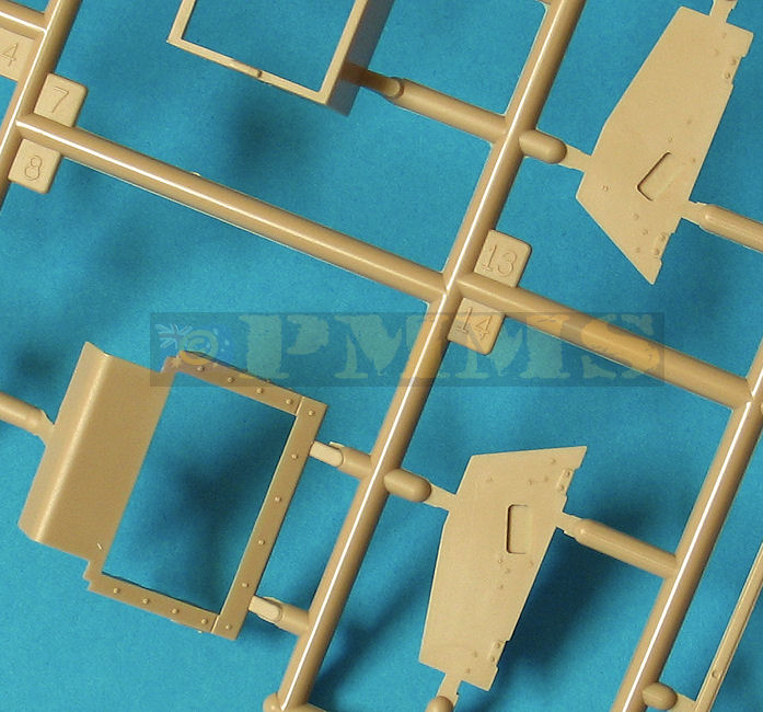
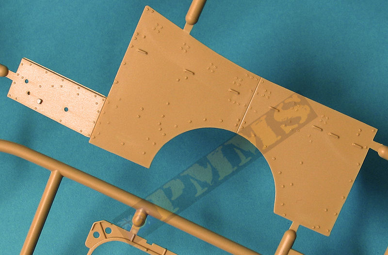
Detail on the parts is good overall with bolt, rivet and panel detail on the hull parts and on the wheel hubs although it is a little basic in places such as the engine and suspension but otherwise perfectly acceptable.
Dimensionally the kit measures out very well against the extrapolated 1:48 plans in the Hunnicutt Armored Car book with measurements for the hull length, width, height and wheel sizes being well within acceptable tolerances for printing etc. individual measurements for side panel segments, hood and skate rail widths and lengths also being spot on give or take a fraction.
The only areas of mention are nit picks such as the rear hull wheel well being about 1mm too shallow and the front mounted roller being about 1mm too wide both of which are not really that noticeable on the final model and not really worth the worry.
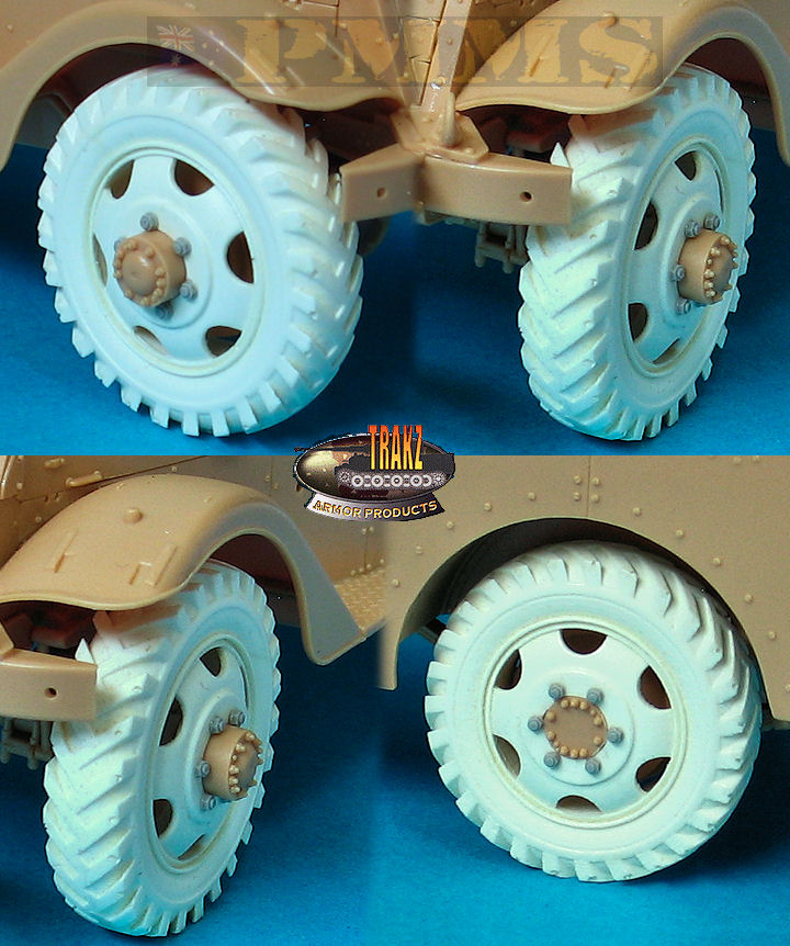
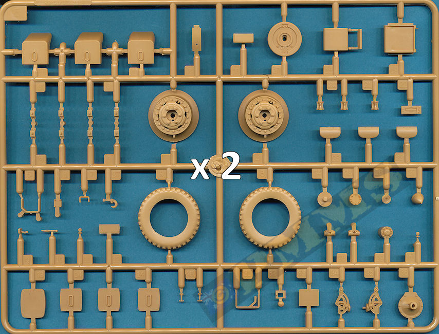
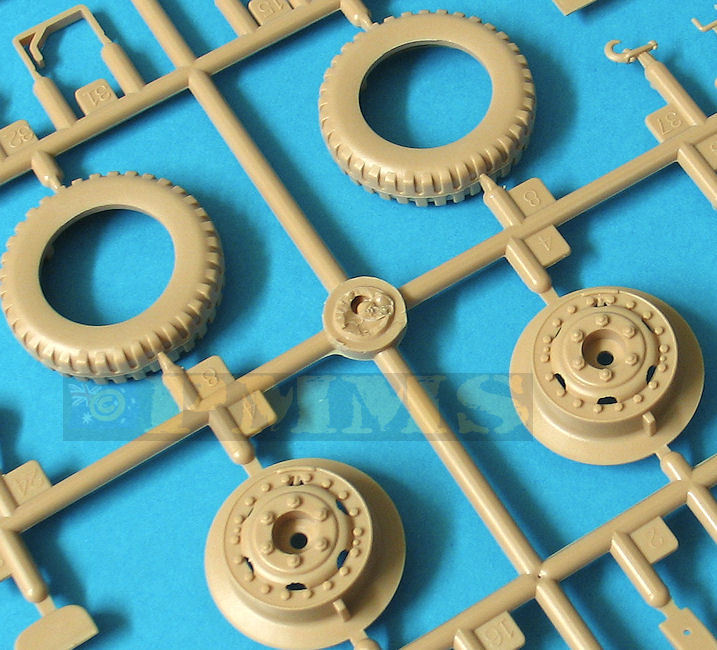
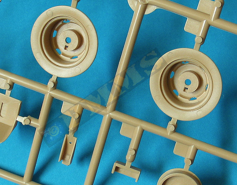
There are a couple areas where there is a mix of early and late features; these being the wheels which are the later standard combat rim and tyre while the early production Scout Cars typically had civilian type rims and tyres with a more aggressive tread pattern as seen in many period photos. Some surviving early production SCs could have been refitted with the combat rim and tyres later in the War and it's best to check references if building a particular vehicle (see marking option 2 below)
Speaking of the tyres these have subtle bulging included, not as pronounced as we have seen elsewhere but have a small flattened area with subtle bulging of the sidewalls, someone forgot to inflate them to the correct operating pressures obviously as there isn’t any bulging on these WW2 cross ply tyres when inflated correctly, but let’s not start up all that again.
The other issue when kit wheels include bulging is you end up with every wheel on every model having the same detail orientation, the rims have the air valves included and due to the bulging the valve is positioned at 2 o’clock on every wheel, this maybe not be that noticeable at first but gives a very unnatural uniform look to the wheels.
The other issue is the two visors on the folding windscreen armour plate are the late pattern and not the simplified early pattern similar to those on the door folding top sections.
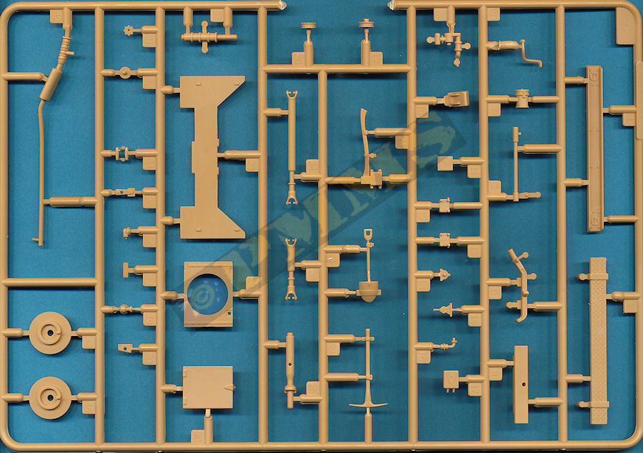
The kit provides a full Hercules JXD engine although this is fairly basic with just the engine block that does have a nicely done head with spark plug detail plus the intake and exhaust manifolds and a few additional engine accessories. The front fan is in etched brass but items conspicuous but their absence is the large air cleaner and the front radiator and as usual adding extra details and wiring will enhance the appearance if you plan on displaying the engine on the finished model?
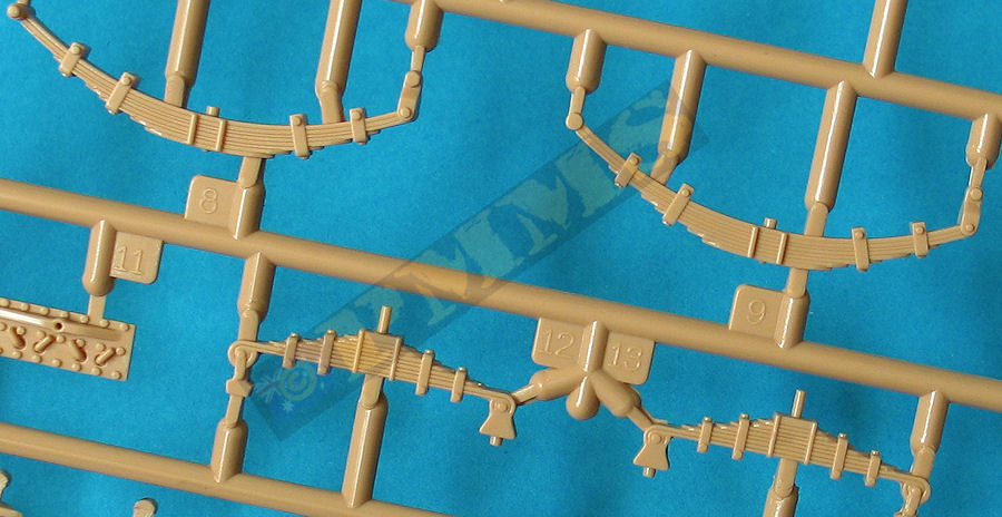
There is a full drive train provided although again some details are a little basic such as the large leaf springs and mountings but overall it gives a good appearance when assembled.
The front and rear suspension/differential/axle assemblies fit together well and have solid locating points on the chassis and are joined to the central transfer case with drive shafts with separate universal joints for a nice appearance and again these all fit together without problems.
The lower transfer case guard (part D36) is on the thick side and will need to be trimmed on one side to fit over the transfer case and the exhaust pipe just sits on the chassis and doesn’t start or end anywhere but as this isn’t seen after assembly probably isn’t an issue.
The wheels as mentioned are the later standard combat rim and tyre and should really be the earlier civilian type for the early Scout Car and hopefully the aftermarket people will come to the rescue (Hussar, Master Productions etc.) with early wheels. Trakz produced a while back a set of early wheels with civilian rims and directional tyres for the DML M3 Half-Track kits and with a little work these can be made to fit to this kit. I think this set is now OOP and as my set was beset with air holes probably a good thing, see images for the modified wheels fitted to the kit to at least show what the appropriate wheel should look like.
But on to the kit wheels and the assembly is quite straightforward but you have to take note of the different part numbers for the front and rear wheel hubs as there are locating notches on the inside of the rims to ensure the “correct” alignment due to the tyre bulging.
The front wheels are fixed in the neutral position and the steering rod and arm are a little on the thick side, also the connecting steering rod (part F5) was slightly too wide and needed trimming to fit between the front wheels, test fitting will determine the amount to be trimmed.
Added to the front is the ditch roller and side support frames with outer bumper sections and the fit was good overall but you must ensure the roller is aligned correctly in relation to the chassis.
The six rear crew seats are in four parts each and are quite nice with no assembly issues and these fit to the compartment floor by way of the locating lugs, plus the centrally mounted aerial post.
The two large wheel well storage lockets have to be glued as snug as possible to the floor section so the outer edges of the lockers are flush with the floor sides, this will effect the fit of the side panels later if not done right here.
The driver’s compartment is nicely fitted out with the two 4 part seats, separate gear shift levers and etched parts for the front louver lever and bracket. The separate accelerator pedal is provided as are the brake and clutch pedals attached to the separate engine compartment firewall added to the front of the floor pan.
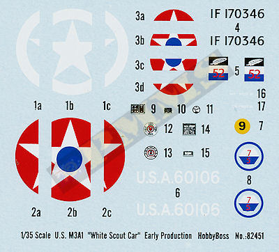
The full width instrument panel has raised detail as well as decals provided for the dial faces and data placards for nice detail, with the steering wheel added to the back of the panel before fitting to the kit later in the assembly.
Added to the insides of the two side body panels are the 14 skate ring supports but as you will find out later these are located too low on the panels to mate properly with the skate ring if fitted as indicated and it’s best to leave these off until all the body panels have been attached.
Jumping ahead a little is the large weapons skate ring mounted on the inside of the body panels so you should complete the body assembly outlined below and we’ll return to the skate ring later.
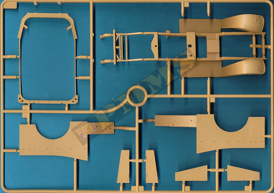
There is a fair few parts shown in the instructions added to the real panel before fitting the panel to the floor pan but as there is some minor trimming needed for the best fit of the body panels it’s best to leave all these off until later. These items include the bumper supports and U shaped bumper bar as well as stowed machine gun ground tripods again with nicely defined details.
There are locating lugs around the outer edges of the body pan that fit into locating holes on the insides of the body panels but it best to trim these lugs a little shorter to allow the panels to sit snugly to the floor pan.
You should also test fit the panels before gluing as I needed to trim the floor pan edges a little for a precise fit of the rear corners, the panel joins are bevelled so when fitting properly there are no gaps requiring filler so this test/trimming is essential as the last thing you want to do is sand filler with all those rivets about the place.
But with the minor trimming of the body pan (not side panels) as mentioned the fit was as intended and didn’t require any filler, you will recall earlier I mentioned the wheel well lockers needed to be glued flush with the side of the floor pan as this also affects the fit if the side panels if they are not perfectly flush with the sides of the floor pan.
Sorry to go on about this a bit but if you do the hard yards getting the fit right of these parts along the way the final result will be far less painful and as can be seen from the build images the fit is excellent if due care is taken but there is scope for real pain if not careful, anyway enough as I think you get the picture?
Once the side panels have been fitted to the floor pan this assembly can be fitted to the lower chassis frame and the fit here is perfect with the body staying in place without glue such is the good fit but of course you would glue it to the chassis.
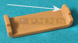
The front armoured radiator is in one piece with four separate louvers that are designed to be movable when trapped in place by the rear radiator panel but conspicuous by its absence is the radiator itself. This means if the louvers are shown open you can see straight through into the engine compartment so it’s best to glue the louvers in the closed position.
You should fit the radiator assembly and engine compartment side panels to the lower chassis in the same operation to ensure they all align correctly and thankfully there was no trimming needed here as with the rear body join.
The instructions show to fit the instrument panel between the two side panels next but I found it better to fit the top T shaped panel first to ensure the proper alignment of the side panels and radiator assembly. Once these panels are securely in place the instrument panel can then be added as I need to trim the locating lugs inside the side panels for the best fit.
Next comes the fitting of the engine hood doors and crew doors and all of these can be shown open if you wish to show off the interior details, there is an issue with the thickness of the hood doors as these are way too thick to represent the panels in the open position. The fit of the hood panels in the closed position was perfect and didn’t require any trimming so this may be the best option and wait for the inevitable AM etched hood doors if you want to show these open in a diorama setting.
The fit of the side crew doors on the other hand did need some trimming to fit and again test fitting is essential as is cutting just very small amounts and re-test the fit instead of one large cut only to find you have trimmed off too much plastic.
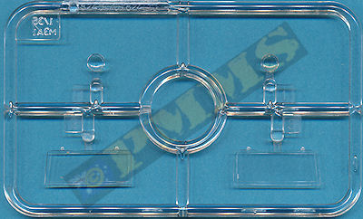
Both doors needed trimming mostly along the rear edge as did the folding top section accordingly but nothing too excessive. The front windscreen has the clear “glass” sections added on the inside and separate wiper blades on the outside and you may want to leave these off until after painting to allow easier masking of the clear parts.
The folding front driver’s armour panel can be fitted open or closed but this has the later style outer sliding visor detail and this should be the early design which is basically a cut-out visor opening with sliding inner cover similar to the visors on the doors for the early version SC depicted in the kit and a little surgery will be required if this is an issue?
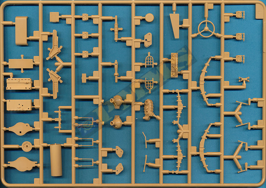
There are numerous smaller details added to the outside of the body once the main panels have been fitted such as the separate hood T latches, the right side storage box, pioneer tools with moulded on brackets and straps on both sides of the body.
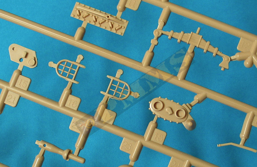
The lights are a bit of a fix with the main headlights with clear ‘glass’ only requiring the electric lead added with the bush guards that do have rather thick over scale mesh and replacing this with thin wire (or sprue) will improve the look considerably. The instructions show four (two each side) small blackout lights fitted to the bush guards but there should only be two (one each side) and the lights are the later style in any case.
There is also a larger black out driving light mounted on the left side of the radiator housing but this is a later production feature and you should leave this off the early production SC depicted in the kit. Two small spot lights are provided mounted each side of the body just in front of the doors (where the jerry can holder goes on the later production SCs) but these were not always fitted so check references if building a particular vehicle to see if these are applicable?
Back to the skate ring, this is made up of three parts, the central ring with front and rear mounting plates and the top and bottom sections that form the lip sections for supporting the weapons pintle mounts. The fit of the skate parts is good but I enlarge the locating holes a little on the central ring for a better fit of the top and bottom sections with the ring fitting snugly inside the rear body and front windscreen but the side fit was a little different.
The rear mounting on the skate ring differs between the early and late style rings, the early mounting is a solid plate between the skate ring and rear body panel while the later style skate ring is attached by a series of U shaped brackets leaving the remaining space open. The slate ring in the kit correctly depicts the early style ring mounting with the solid mounting plate.
As mentioned above the position of the mounting brackets (parts E3) don’t align with the skate ring if fitted as indicated and it’s best to dry fit the ring into the hull and the snug fit front and back will help considerably with this.
You should then mark the correct positions of the mounting brackets so they align between the upper and lower lips of the slate ring then remove the ring and glue the brackets in the new positions. Once dry you can then refit the skate ring, you may have to flex out the side panels slightly to fit the ring over the brackets but the ring will stay snugly in place without gluing if you wish?
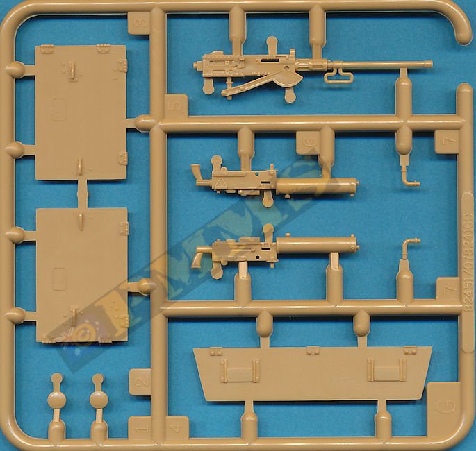
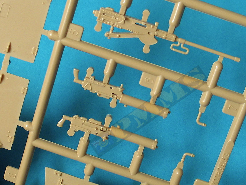
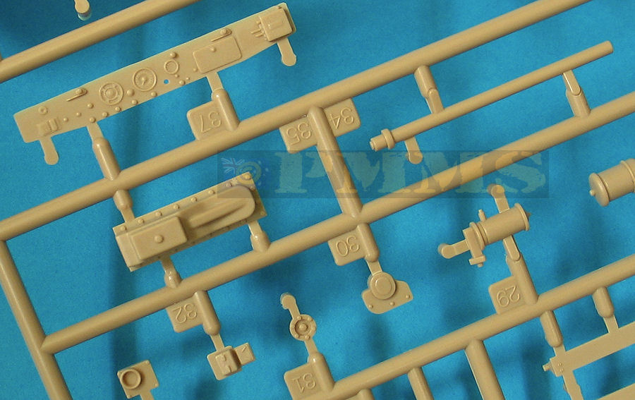
The cal.50 is also a little chunky with heavy detail on the barrel changing handle, receiver and rear firing handles and the barrel is a little short but does have the correct size bore hole included.
There are also two early M1917A1 cal.30 water cooled MGs fitted to a two part cradle with ammo box attached, unfortunately the MGs don’t include the water tank and attachment tube as they should and these will have to be added for an authentic setup.
Both the cal.30 and cal.50 MGs are mounted on multi-part M30 carriages made up of seven parts each and build into nice looking mountings, the assembly of the carriage is straightforward but you should let the glue dry completely before attaching to the skate ring and these can be located anywhere around the skate ring as that is what it’s designed for, to easily slide the MG mounting to wherever the threat is.
The other is overall dark green with black cam with markings for a New Zealand vehicle from C Squadron, 20th Armoured Regiment near Triests, May 1945.
Note: Photos show this vehilcle had been refitted by 1945 with the later Combat wheel and non-directional tyre as included in the kit.
Option 1:
Unidentified U.S.Army unit |
The overall fit of parts is good but a little trimming is needed with some body panel fit but nothing excessive and easily dealt with and there is scope for adding additional detail as with any kit.
This kit is a vast improvement over the ancient Peerless Max kit and all it’s descendants which has been the only game in town till now with this kit now being the weapons of choice for the M3A1 Scout Car builder.
Rating 8/10
Click on thumbnails for larger view
Build images
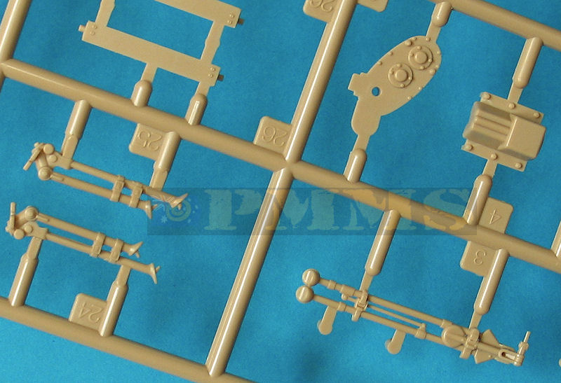
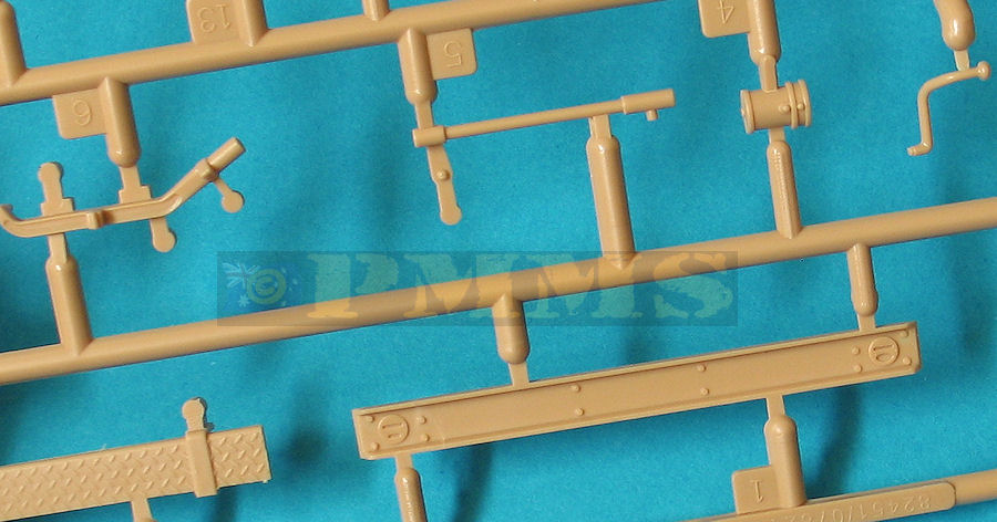
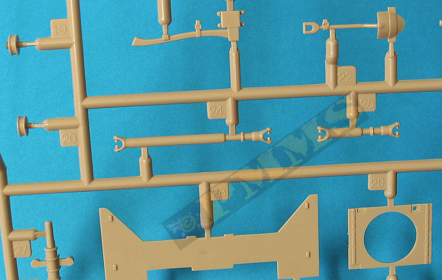
Sprue Detail Images

| Armored Car A History of American Wheeled Combat Vehicles R.P Hunnicutt ISBN 0-89141-777-X  |
M3A1 Scout Car Walk Around Squadron Signal Publications David Doyle  |
| Allied & Axis 12 Ampersand Publishing Soft cover, 96 pages  |
Thanks to my credit card for the review kit.
