
Morris Commercial C8 Quad
SKP Model 1:35 Scale Kit No. SKP 190
Review by Terry Ashley
The kit includes optional doors with and without the windows but as the solid roof restricts the model to the Mk.I, early Mk.II only the solid doors should be used, also the smaller side windows have the frames for the smaller windows on both sides but those on the far side need to be removed to give the flat side wall for the Mk.I/early Mk.II.
As well as the main resin parts the kit also comes with additional etched parts plus clear sheet for the windows and etched/clear resin parts for the lights along with a decal sheet and eight page A5 sized colour instruction booklet, the full contents is:
- 84 parts in light blue resin
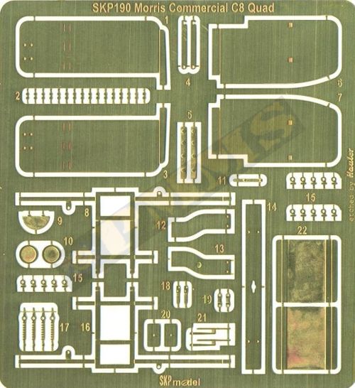
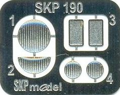
- 78 etched brass parts
- 1 clear sheet with nine window templates
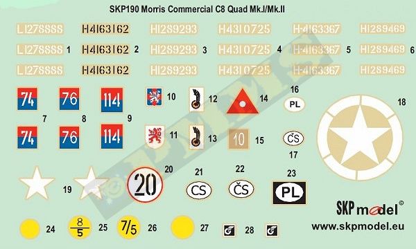
- 1 decal sheet
- 1 eight page A5 instruction booklet
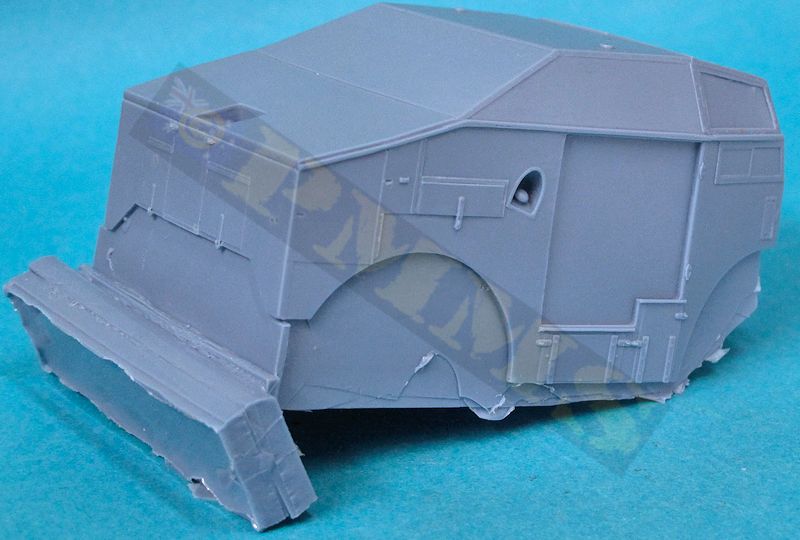
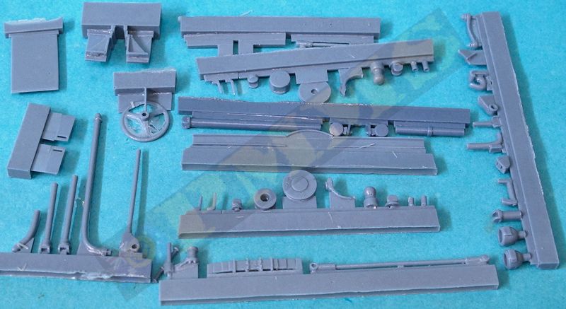
The standard of resin casting is very good overall with clean crisp detail and just a minimum of excess resin ‘flash’ to be removed along with the usual casting blocks, there are huge blocks on the body shell and floor castings that will need to be removed using a razor saw while the blocks on the other parts are more reasonably sized and can be removed with either razor saw of snips depending on your preference. There are only a few air holes in evidence, some in hidden or hard to see places as well as some ‘under surface’ air bubbles, these can be seen but if the surface isn’t disturbed will disappear when painted. Some additional air holes were exposed when removing the casing blocks such as on the tyres and a few other parts and filling any that show up before assembly is best. It should be noted that as with any resin kit the results of the resin casting can differ from kit to kit, so the comments here and below about the resin casting blemishes may vary between kits.
The resin while having crisp detail is not overly brittle having a softer quality (while still being hard if that makes sense?) making it quite easy to work with which aids when cleaning up the casting blocks but this “softness” leads to a quite dramatic issue with “axle sag” after assembly due to the weight of the built kit on the fairly thin axles. This issue didn’t manifest itself until a day or so after I had built the kit, so all the build images are as “normal” and I’ll also describe the assembly also as “normal” bearing mind you have to strengthen the axles beforehand as per the section I have added at the end to address the axle sag issue. Obviously with hindsight these steps need to be taken before assembly to deal with this as we’ll see below.
Dimensionally we have a bit of a conundrum, not so much because of the kit but with available references that indicate conflicting dimensions on the vehicle size. Taking the width for example we have the following data from the references listed below:
Capricorn book has the width listed as 7’5”, scale size 64.6mm
Capricorn book 1:35 plans has the width of 67mm
MV8 book has the width listed as 7’3”, scale size 63.15mm
Tankograd book has the width listed as 6’11”, scale size 60.2mm
Wikipedia has the width listed as 7’3”, scale size 63.15mm (same as MV8 book)
The kit has a width of 62.5mm, somewhat at the lower end of all those stated dimension so this leaves you scratching your head and without definitive dimensions I can’t make an accurate call on the kit overall dimensions, there a few smaller individual dimension issues around the engine compartment but more on this below.
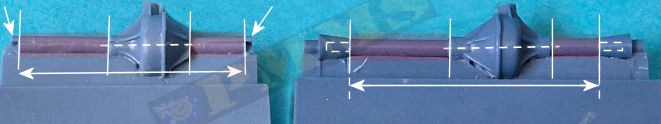
As mentioned I had fully assembled the kit before the issue of sever axle sag manifested itself, so before assembly you should modify the axles as per this guide, click header to expand.
I’ll then continue with the assembly but note the assembly images show the kit before these axle changes were done.
1. Draw a template on paper for the length of resin axle to be removed.
2. Cut the half circle stub from the end of the axles and glue these into parts A36 to fill the hole in these parts.
3. Cut away the axles (shaded in image)
4. Drill a 2.5mm hole through the differential, ensuring it is perfectly central.
(drill from either side meeting in the middle instead of drilling one direction, this helps get the holes aligned.)
5. Replace the axles with a single length of 2.5mm brass tube (tube, not solid rod)
6. Determine the diameter of the inside of the tube and use a corresponding diameter wire (or thinner brass tube) to extend from the
brass axle tube into the wire sized hole drilled into parts A36 and attach parts A36 to finish the modification.
7. Assemble the suspension from here as per instructions.
Rear Axle:
1. Again draw a template on paper for the length of resin axle to be removed.
2. Cut off the angled end sections from the axle.
3.Cut away the axles (shaded in image)
4. Drill a 2.5mm hole through the differential, ensuring it is perfectly central.
(drill from either side meeting in the middle instead of drilling one direction, this helps get the holes aligned.)
5. Replace the axles with a single length of 2.5mm brass tube (tube, not solid rod)
6. Determine the diameter of the inside of the tube and use a corresponding diameter wire (or thinner brass tube) to extend from the
brass axle tube into the wire sized hole drilled into angled end sections from the axle and re-attach the end sections to finish the modification.
7. Assemble the suspension from here as per instructions.
Note: you still need to add the small plastic block "spacers" as above to prevent the leaf springs compressing.
See the full modifications and extra details added in section 4 of the assembly images below
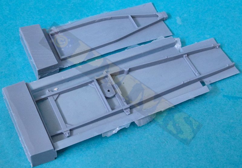
The front axle/differentials can be assembled to allow the front wheels set at an angle to give some steering animation to the kit but the parts are not designed to be movable after assembly, so choose the attitude you want the wheels before assembly.
After attaching the ball mountings (parts A36) to the axles the cup wheel hub is added at the steering angle you choose along with the steering arm linkages and rear universal joint. The leaf springs are best glued to the chassis before attaching to the axle as there are no locating marks on the axle for the correct position. The attachment lugs on the leaf springs need to be cleaned out inside for a smooth inner surface to allow these to fit properly to the chassis frame and once done fit very well to the chassis. The axle can then be added ensuring the equal part of the axle extends outward of the springs on either side.
Once attached the additional steering linkages can be added to the front suspension, just note the steering rod on part A56 should be cut off as there in nowhere for it to go once the floor is fitted, this will become obvious at the time. The rear leaf springs also have positive locating points on the chassis but again make sure the mating surfaces are perfectly smooth for a better fit and again make sure the axle is fitted centrally over the leaf springs when gluing in place.
Before attaching the chassis to the body the main body shell and floor have to be fitted together so we’ll come back to the final chassis assembly later.
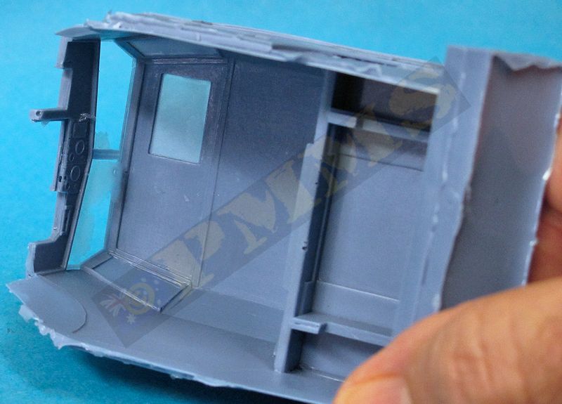
Just a sidenote with my kit, due to casting the front windscreen frame was wafer thin and I added thick cyanoacrylate to the inside to give some added strength but this needed care not to damage during assemble and as noted this may not be the same on all kits due to varying casting between resin kits. The windscreen on the actual vehicle can open with top hinges but is cast firmly in the closed position on the kit while the kit provides etched windscreen wipers for nice detail.
The windows need to be added next with the main windscreen cut from the clear sheet provided and added from the inside of the body shell, this also helped stiffen up the thin screen frames in the process. The upper angled windows if cut as indicated on the clear sheet will be too small so overlay the clear sheet to the opening and check the correct size to cut. The smaller windows will also need test fitting before cutting to get a proper fit.
On the inside front of the body is the engraved instrument panel dials but there were a few large air holes here that will difficult to see after assembly, the steering wheel is also added with a steering column added from plastic rod not included in the kit.
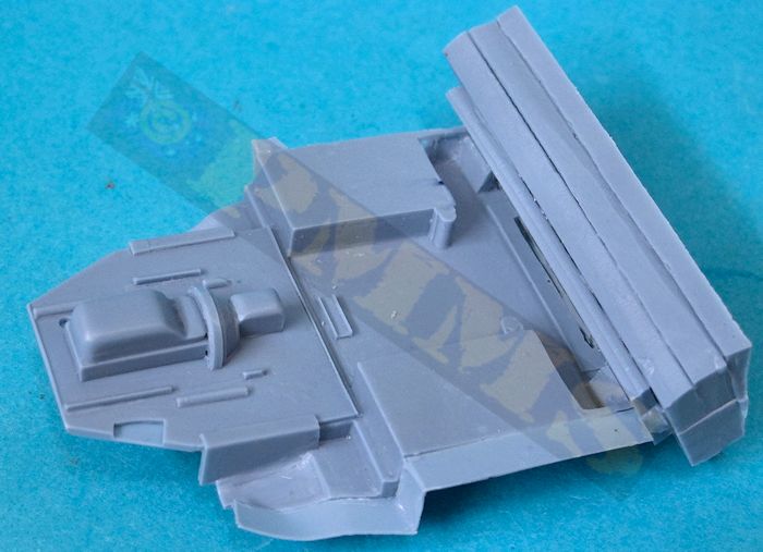
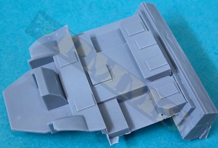
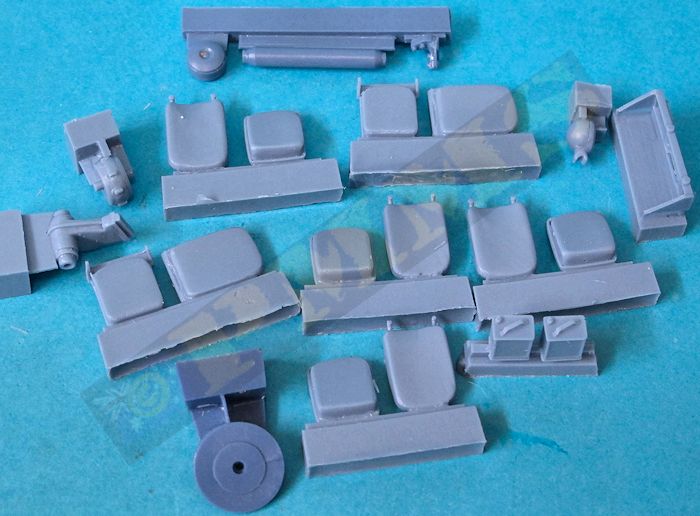
We move to the floor and seats next as well other smaller details; these are all fairly basic with just the hand brake and engine air cleaner provided but no gear levers or driver’s foot pedals so these can be added if you are planning to leave the large side doors open?
The seats are again fairly basic but adequate, just make sure the rear backrests are glued inside the line of the floor or they will compromise the fit of the floor into the body later. The fit of the floor into the body shell is very good with the front aligning well and the rear slipping over the raised central locating recess for a positive location. Once glued in place the two large underside fuel tanks can be glued to the floor and body sides to provide additional strong attachment points with the only modification being to trim the central underside of the floor smooth as there is a raised ridge that should be removed, see assembly images.
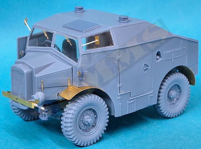
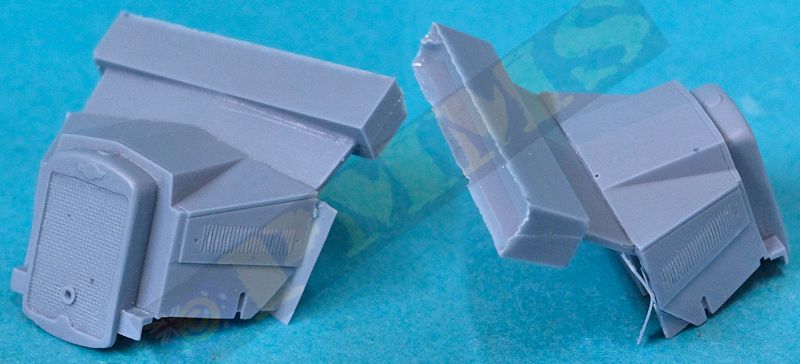
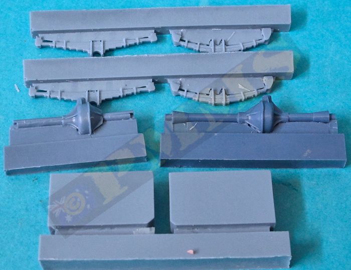
The engine compartment is a solid casting but the hood contours are out a little with the compartment not tall enough and the side angle being too shallow which results in the length of the top edge of the hood being too short, see the image for better explanation. The side louvers are not that well defined and the radiator included with the casting is unfortunately about 2mm too narrow and should extend further towards the edges of the bodywork. Also the texturing of the grill is very basic and the radiator cap is missing although this can be added from the piece of plastic rod.
The fit to the engine compartment and the body is good but I needed to push the bottom of the windscreen out from the inside of the cab to join the top of the engine hood properly otherwise there would have been a large gap. You also need to make sure the engine compartment sits perfectly evenly on the floor pan for the best alignment. The side latches are supplied in etched brass for nice detail.
The instructions indicate in step 11 to fit the two rear chassis support bracket (parts A14, A15) but these are best left off until fitting the chassis as there are no precise locating marks and they have to align with the chassis so fitting these along with the chassis is a better option.
The drive train is added next this has the transfer box with front and rear drive shafts and universal joints, the rear drive shaft is in two parts with the narrower shaft fitting inside the larger shaft, I drilled out the rear larger shaft a bit further as this made it very easy to fit the drive shaft as you slide one into the other and then extend out to mate to the rear differential and front transfer box.
The space for the front drive shaft and universal joins is too small and they simply won’t fit so I cut back the front section of the transfer box to allow the universal joins to fit, there isn’t an actual drive shaft here as there isn’t room so you need to cut down the parts provided to fit, which is fairly easy to do with test fitting along the way. One thing that is missing is the drive shaft from the engine gearbox on the underside of the floor pan to the transfer box but you can’t see this after assembly but can be added if you wish?. The three part exhaust pipe also fits very easily to the locating points provided.
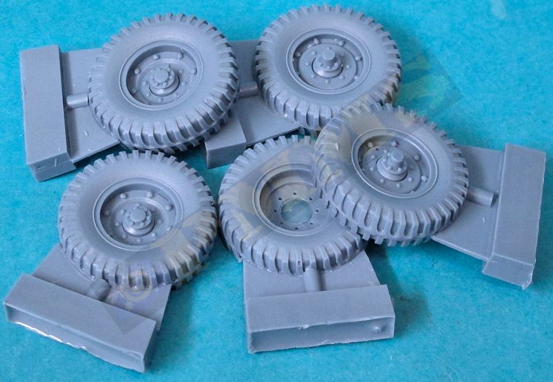
Fitting the wheels is quite straightforward although the hole in the back of the front wheels is too big for the axle pin but thankfully the pin is long enough for you to drill a smaller hole in the wheel for the pin for a more positive fit. The rear wheels fit snugly to the axle pin just ensure the wheels are set vertical before the glue cures.
The many smaller detail items and etched parts can now be fitted these include the fenders that need to be bent to the curve profile before fitting but there is a small issue to watch for on the front fenders. There are small indentations for the location of the top etched bolt strip but the these indentation make a weak point and when bending the brass wants to bend more due to these weak points so take care. Thankfully it’s only a slight curve so this isn’t a big problem but make sure the bend is an even curve over the indentations.
Fitting the fenders is a little tricky as the exact locating points are not that clear so test fit often before finally gluing in place. You have to add the wire (not supplied) front fender supports with small kink bends in the wire.
The front bumper bar has small curves at either end and there are multiple engraved bend lines on the rear of the bar that make it easy to get a smooth bend and it’s best to attach the support brackets (parts F12, F13) to the bumper bar before fitting to the body. You do need to ensure the bumper bar is positioned perfectly horizontal and level with the crank handle hole in the radiator and also set correctly on the chassis sides as there isn’t any locating marks.
Other details include the etched bolt strip on the fenders, the single main head light which has alternate etched flap cover or resin “glass”, most wartime images show the etched flap is the more common and you need to provide the short plastic rod mounting post for the light. There are also the two small side lights on the body side with again the clear resin glass for a nice appearance but they do appear to be slightly oversized from available images. The two rear view mirrors are in etched and resin with a small attachment bracket for the mounting post you again provide from this plastic rod or wire. I prefer plastic rod inserted into a hole drilled into the body frame as this allows some give if you touch this while handling the model.
Also provided for the rear are two fine etched “flimsy” can holders but I didn’t fit these as I simply could not work out from the instructions how the support arms should be bent to fit to the rear body and fenders, additional reference would be helpful in fitting these.
There are a couple of notable detail omissions from the kit, the first is the tow shackles on the front chassis which can easily be made from thin wire and the large cargo rack mounted on the rear body deck. I built this from thin plastic rod using reference images to judge the size, the spare kit wheel should be able to fit into this rack but there are not actual mountings for the spare and it just “sits” on the rear deck as if by magic.
- 1:
Morris Commercial C8 Quad Mk.I, Czechoslavak Mixed Brigade, Artillery Battalion, Leamington Spa, March 1941.
- 2: Morris Commercial C8 Quad Mk.II, unknown unit, North Africa, March 1942.
- 3: Morris Commercial C8 Quad Mk.II, Czechoslavak Independent Armoured Brigade Group, Artillery Regiment, Prague, May 1945.
- 4: Morris Commercial C8 Quad Mk.II, 1st Polish Armoured Division, 2nd Motorised Artillery Regiment, Scotland, October 1943.
The only real dimensional issues are mostly with the engine compartment but due to lack of information I can’t comment on the overall vehicle dimensions at present but it does seem in proportion compared to photos of the actual vehicle.
Being a full resin kit with additional etched parts this kit isn’t for the inexperienced modeller but with only minimal work a nice model will result and there is scope for adding additional details if you wish in and around the vehicle.
Rating 7.5/10
Click on thumbnails for larger view
Resin part images


| Morris Commercial C8 Quad Army Wheels in Detail #3 Capricorn Publications  |
British Military Trucks of WWII Tankograd Publishing ISBN: 978-3-936519-29-7  |
Morris C8 Military Vehicle Series MV8 Inkpen Art Productions (OOP)  |
Thanks to SKP Model for the review kit.
