
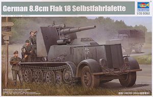
German 8.8cm FlaK 18 Selbstfahrlafette
Trumpeter 1:35 Scale Kit #01585
Review by Terry Ashley
Approximately 4,000 were produced between 1938 and 1945 with main contractor being Daimler-Benz with others built by Krupp, Krauss-Maffei and Škoda, the DB s8, DB 9 and DB 10 were provided by a Maybach 12-cylinder, 8.52 litre HL 85 TUKRM gasoline engine of 185 horsepower.
While the majority of Sd.Kfz.8s was built as artillery tractors some were converted for other uses, the most notable were the ten 8.8 cm Flak 18 (Sfl.) auf Zugkraftwagen 12t (Sd.Kfz. 8) vehicles with modified 8.8 cm Flak 18 anti-aircraft guns mounted on rear pedestals, all these were all built on the DB s8 and DB 9 chassis. These vehicles were used by Panzerjäger-Abteilung 8 during the invasion of Poland in 1939, the Battle of France in 1940 and Operation Barbarossa in 1941; the last three vehicles had been lost by March 1943.
The kit also includes the armoured engine compartment panels and armoured cab along with the modified 8.8cm FlaK 18 that has a choice of plastic or metal barrel as well as the modified shields again in a choice of plastic or etched brass plus the large ammo rack on the rear hull for an impressively detailed kit OOB.
The only set of 1:35 plans available to me were in the Nuts & Bolts Volume 16 listed below but these contain some obvious errors so doesn’t do a lot for confidence although the overall dimensions match available data okay, it’s just some of the smaller details with the discrepancies. As no DB 9 chassis vehicles survive today we only have a dozen or so period photos to rely on and the comments below are based on the observations from published data and those photos.
The kit dimensions do match the plans overall except in a few lesser areas as well as matching the available period photos in most areas with one notable exception with the drive sprockets that we’ll get to below. The 8.8cm FlaK 18 also matches available plans available in quite a few references well overall with again just some minor variations that probably are not worth getting excited over. One notable feature with the 8.8cm FlaK 18 is it is very reminiscent of the AFV Club 8.8cm FlaK 18 (kit #AF 35088) released some years back in most part breakdown, detail and the use of metal parts with just a few alterations in the parts for the 12t mounting. I’m not sure if there has been any collaboration or Trumpeter just didn’t want to re-invent the wheel, in any case it results in a very nicely detailed 8.8cm gun for this kit.
The kit consists of:
- 481 parts in light beige plastic
- 250 individual track links in chocolate coloured plastic
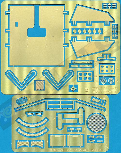
- 57 etched brass parts
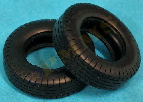
- 2 vinyl tyres
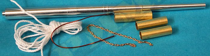
- 1 metal 8.8cm barrel tube
- 1 length of fine chain
- 1 length of brass wire
- 1 length of twine
- 3 short brass tubes
- 2 small decal sheets
- 1 20 page instruction booklet
Assembly of the engine is straightforward without any problems and like any engine additional detailing can be added to make a standout engine if being displayed on the finished model. The two long exhaust pipes are in multiple parts and added after the chassis has been assembled.
Sitting just behind the engine is the large gearbox with good detail, this gearbox is also slightly modified from the previous kit gearbox to fit the new chassis but as none of this can be seen after assembly it’s of no real importance anyway.
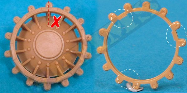
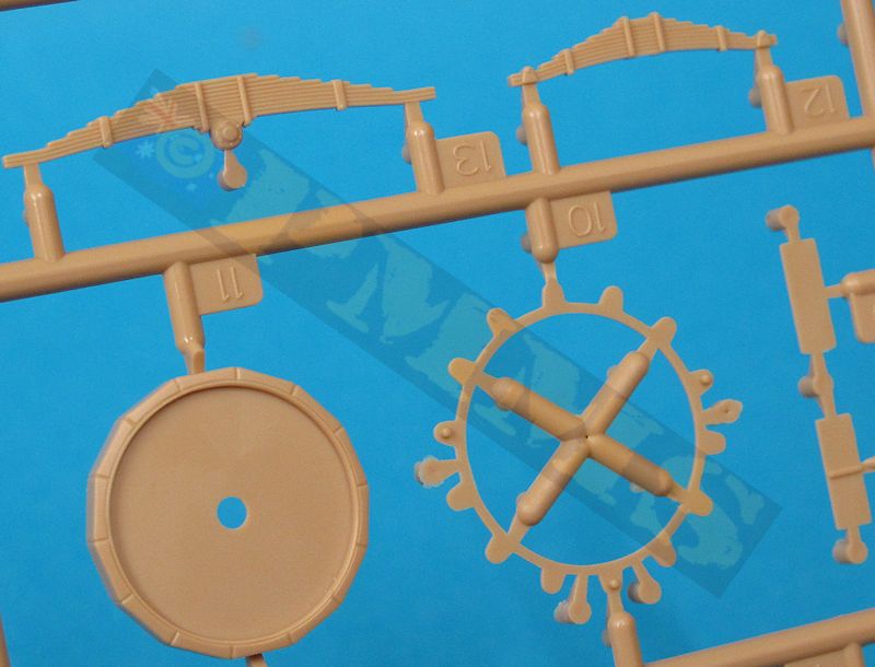
The drive sprockets are sized correctly and have a separate drive roller (teeth) discs and central hub cap with textured etched strips for the footsteps but there are a few issues with the sprockets.
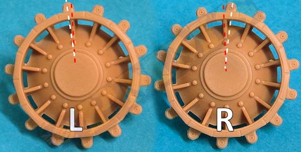
First is the drive teeth (rollers) are not offset as they should be. The rollers on all German half-tracks were offset towards the front (left and right sides) of the flat track pad section of the sprocket to allow the roller to intermesh with the tracks correctly. Again this is quite noticeable given the size of the sprockets but it is very easy to fix by just cutting off the locating tabs on the inside of the separate tooth rings (parts B22) and fit with the rollers aligned correctly for the right and left side sprockets.
as per above.
Images showing the correct offset of the drive rollers for the left and right drive sprockets.
The second is the sprocket ribs extend out to the edge of the rim but period photos clearly show the ribs sit on the inner edge of the outer rim leaving a smooth rim around the sprocket and to fix this would take a far bit of effort to remove and reposition the ribs.
The final drive housings are quite basic but you can’t really see this anyway with the sprockets fitted and the inner sprocket half is first attached to the final drive by way of the small pin which allows the sprocket to rotate. The other sprocket sub-assembly (tooth ring and outer sprocket half) is then attached to the inner sprocket half and the full assembly can be added to the chassis.
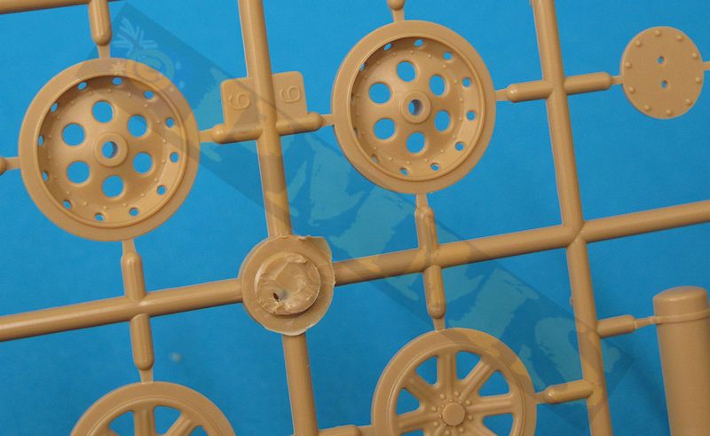
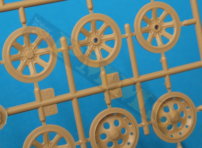
The road wheels are sized correctly and have the rim and hub details quite nicely done, the rim bolts could be a little more defined but that is probably nit-picking, the idlers also include the inner tooth rods as they should do and overall the wheels are nicely done.
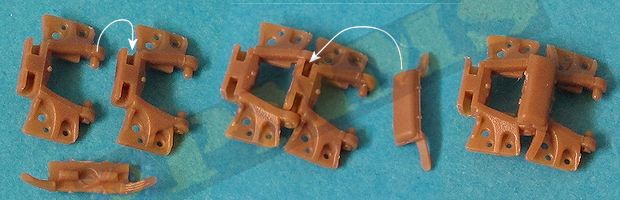
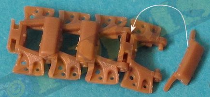
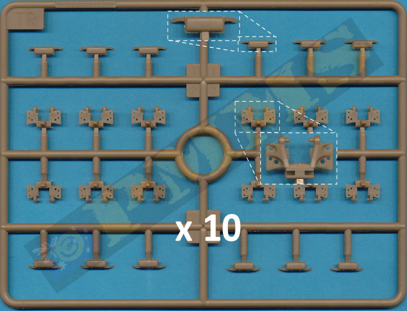
The Zgw 50/400/200 tracks sees the 400mm width equalling 11.428mm in 1:35 scale and the kit tracks at about 11.5mm give or take a fraction so are perfectly okay in size. The individual link workable track is broken down in the usual manner for German Half Track kits with the track link and separate rubber pad that traps the pins from the previous link during assembly to form the workable track runs. The rubber pad sections also include part of the track rib on either end of the pad to give a good definition to the links but you need to take care not to damage these extensions while removing the pads from the sprues.
One small issue is the pitch (length) and each kink is fractionally too short, this results in 56 links required for each track run when the actual vehicle used 55 links per side, the difference of one track link is something you wouldn't loose sleep over at the end of the day. The assembled track runs articulate well and fit perfectly around the sprockets providing you made the minor alterations when fitting the tooth roller rings as above.
This is repeated for each track link for the 56 required for each track run.
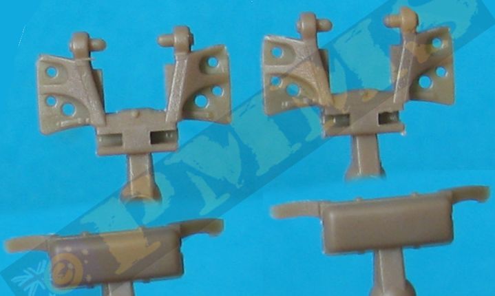
The springs are trapped between the two mountings frames (parts B7,B9) with the large A frame brace added to the rear of the axle and the steering arms attached to the small mounting brackets, just make sure the glue on the brackets (parts D16) is completely dry before fitting the steering rod (part B18).
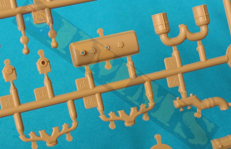
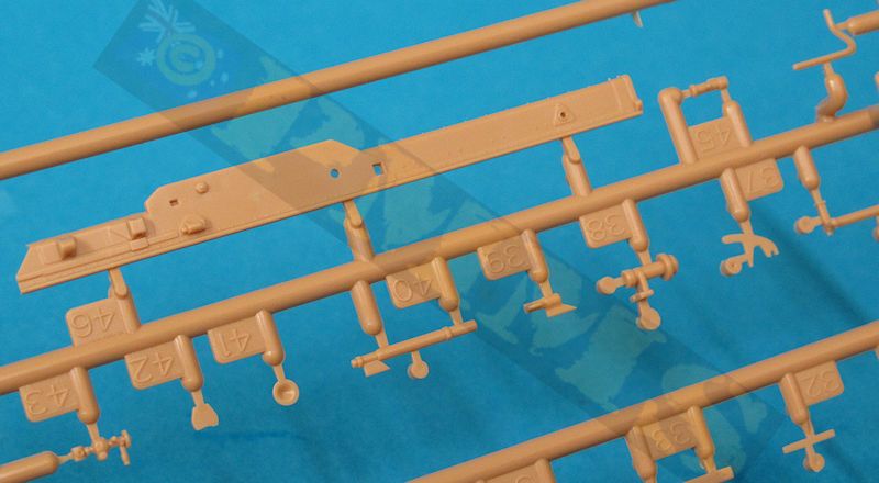
The chassis has the two large side beams separate joined together by the two transmission support beams, the large rear bulkhead with multi-part towing hitch assembly and the front axle sub-assembly. There are additional smaller mounting beams for the winch motor, the three compressed air tanks and rear mounted ammo box rack and all these have to be fitted between the chassis frames in the one operation ensuring the chassis is perfectly square and level without any warping before the glue dries. I found the two transmission cross beams and the rear towing bulkhead gave a good solid join which was nicely square in the first place so the alignment was good to start with.
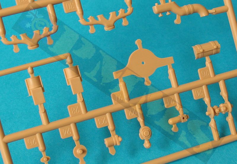
Before fitting the two part winch drum you may want to add the thread provided for the winch cable but as you can’t see the winch after assembly it wouldn’t be missed unless you wish to show the cable extended out the back after assembly.
The bogie leaf springs are added to the chassis sides and again the springs are in two halves to give clean side detail and are easily fitted to the chassis mountings along with the rear idler spring and adjustment arm, the instructions also show to fit the front steering column to the chassis but this is best left off and attached to the engine firewall instead for easier assembly, but more on this below.
The two large multi-part axle mounting sub-assemblies fit together well but you must ensure all the parts are fitted square and evenly spaced as some of the mating surfaces are not that even and can result in the side axle mountings sitting at an angle if not careful. These large sub-assemblies fit snugly to the chassis frame with the leaf spring ends locating on the ends of the assembly arms for a robust assembly. The twin axle stubs can then be fitted to the mounting and these have a long and shorter axle and you should ensure the longer axle is at the rear of each station. It’s also best not to glue the axles in place to allow for any movement to align the wheels evenly when fitted later.
At the front are additional steering linkages and these are designed to be glued in place and negate the movable axle stubs but do allow you to position the wheels at an angle should you wish a bit of animation. As the linkages are fairly sizable it would be an easy task to add small pins and drill corresponding holes should you want to make the linkages movable for fully steerable front wheels?
Final assembly of the chassis sees the engine added and the fit was very good not requiring any adjustments plus the front wheels, drive sprockets and road wheels/idlers, there were again no problems fitting any of these just take care fitting the interleaved road wheels to ensure they all align together and sit evenly along the ground line unless you want to articulate the running gear if displaying the model over rough ground in a diorama setting.
The track also fits well and any adjustment for the right amount of track sag can be made by adjusting the position of the idler axle that you left unglued from before, didn’t you?
Added to the top of the fender cross section is the three part radiator housing with separate top filler cap and rear radiator insert, there is also etched radiator mesh added inside the radiator insert but this was too big to fit and needed the diameter reduced with careful filing until it fitted better. This whole radiator sub-assembly is all but hidden after the armoured cover is added but you can see it through the small amour plate spaces so you should add it to avoid the empty ‘see-through’ look if not fitted.
The engine firewall is designed to slip in between the drive sprocket fenders attached to the hull top deck just behind the engine air cleaners while at the same time feeding the steering column through the hole in the firewall, this is quite a tricky process as there is not a lot of room to manoeuvre. A far easier solution is to not attach the steering column to the chassis as indicated but to glue this to the firewall instead; this makes it far easier to fit the firewall in place with the base of the steering column lining up with the chassis you can’t see this after assembly so it’s not a big deal not being glued to the chassis. There is also a delicate etched steering column brace added between the column and the firewall and attaching the column to the firewall also makes it a lot easier to fit the brace before you fit the firewall to the chassis, making life a lot easier all around.
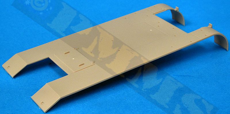
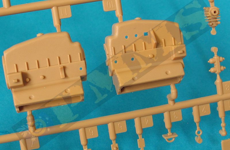
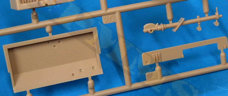
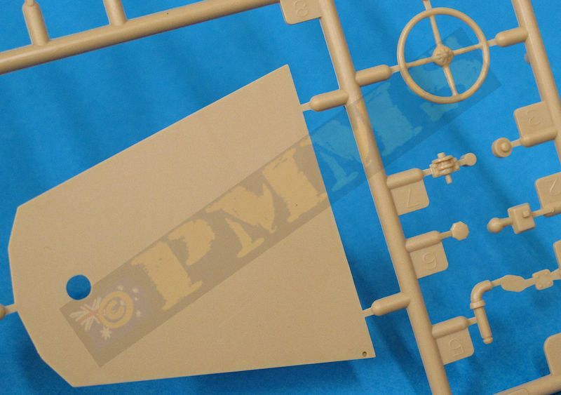
The driver’s compartment floor pan is a separate part with tread plate texturing to which is added the three gear levers and foot pedals, the floor fits neatly into the hull deck without any problems. Attached to the rear of the firewall is the full width front panel with three rear mounting brackets and a separate speedometer, two small etched levers along with the instrument panel, this is attached on the right side of the panel which appears a little odd but as there are no clear photos of the vehicle panel I can’t say if this correct or not but being located centrally would seem more appropriate based on other half-track layouts? There is also the two part oil tank located behind the instrument panel plus the driver’s seat and large storage box on the right side; this has small etched latches for added detail.
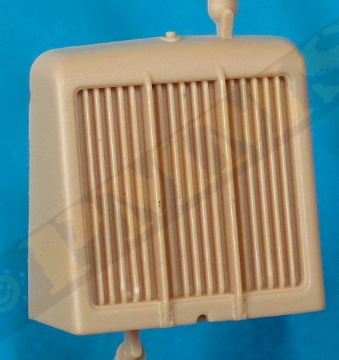
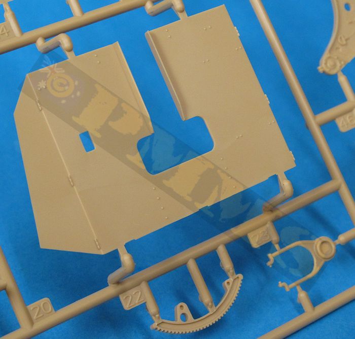
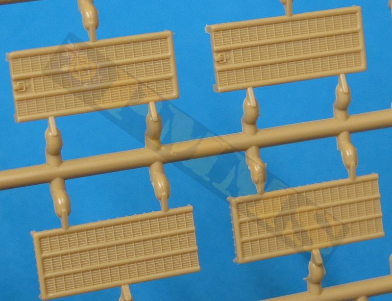
The armoured engine compartment is made up of five flat plates with separate cooling panels with separate grab handles on the sides; all the panels fit neatly together without any problems. The panels have the open gaps between them after assembly as they should and it’s best to assemble the compartment before fitting to the hull for easier handling and the compartment sub-assembly also fitted precisely to the hull without problems.
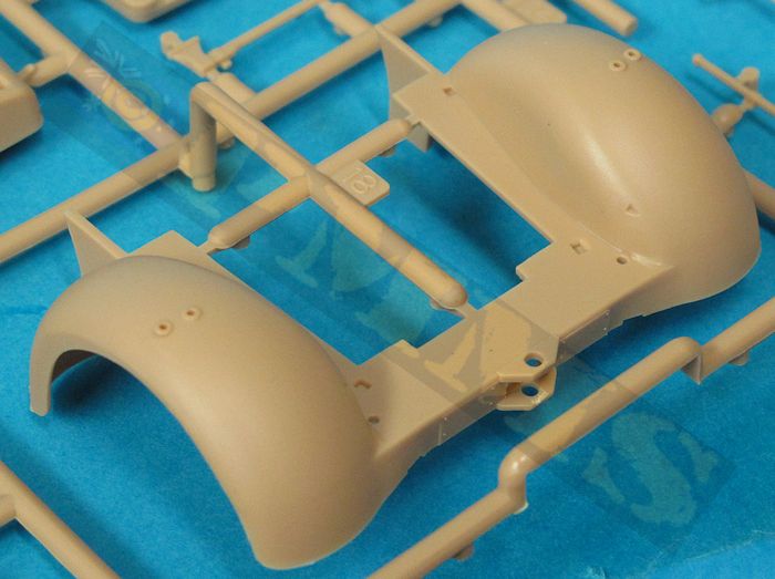
Other details added are the side indicators and driver’s mirror post with the front bumper bar and head lights added. The head lights are in plastic with etched housings that need to be carefully bent to shape using an appropriate sized drill bit as a former for the top bend to get and even bend. The front flap can be assembled open of closed as required with the inside light and mounting post attached using cyanoacrylate before fitting to the front hull. I needed to file some metal from the back corner of the right hand light to clear the fender but test fitting will determine if any adjustment is needed. Etched steps are also added between the front and rear side fenders and the outer edge has to be bent to form a rounded curve and care is needed to get the bend in the right position before fitting.
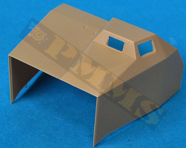
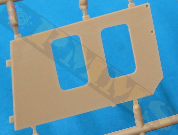
The large armoured cab is moulded in a single large part with the angles appearing okay compared to period photos, the only additions are the two driver’s visors with inner detail and the barrel travel lock that comes with two style of moulded plastic chain, one open and one closed around the barrel. The plans show the sides of the compartment as a little too tall but as mentioned above these are not totally reliable and the cab doesn’t look out of scale compared to period photos. One clear error in the Nuts & Bolts plans is they show a visor on the right side of the driver’s hood but photos clearly show this is not present only the left and front visor as correctly depicted in the kit.
The cab fitted to the hull deck without any problems and note the sides don’t actually mate with the armoured engine compartment sides but sit inside the outer compartment panels with a small gap so don’t worry if this appears as a miss-match.
Pioneer tools are added to the cab fenders and cab sides with the axe and shovel having moulded on clips while the five part jack has separate attachment clips although these would be better represented in etched brass with plenty of detail sets available with jack clips.
At the back are the two small taillights with etched brackets and etched mud flaps plus the large ammo storage box and etched rack, the box is made up of six sides with bevelled edges for a very good fit that doesn’t need any trimming or filler. The top etched rack is held in place with small pins on the box fitting into corresponding holes in the etched frames and these fit well for a positive fit. The wicker 88 ammo cases are in two halves with a side join seam but this is not that noticeable due to the wicker texturing, the cases have separate tops but are not designed to show open with the rack holding five ammo cases. If you wanted to build the cases open you would need to thin down the insides considerably to allow shell cases to fit, not an impossible task.
Finally there is the large pedestal gun mounting fitted to the centre of the rear deck, note the locating holes are not symmetric so just turn the pedestal until the holes line up with the pedestal pins.
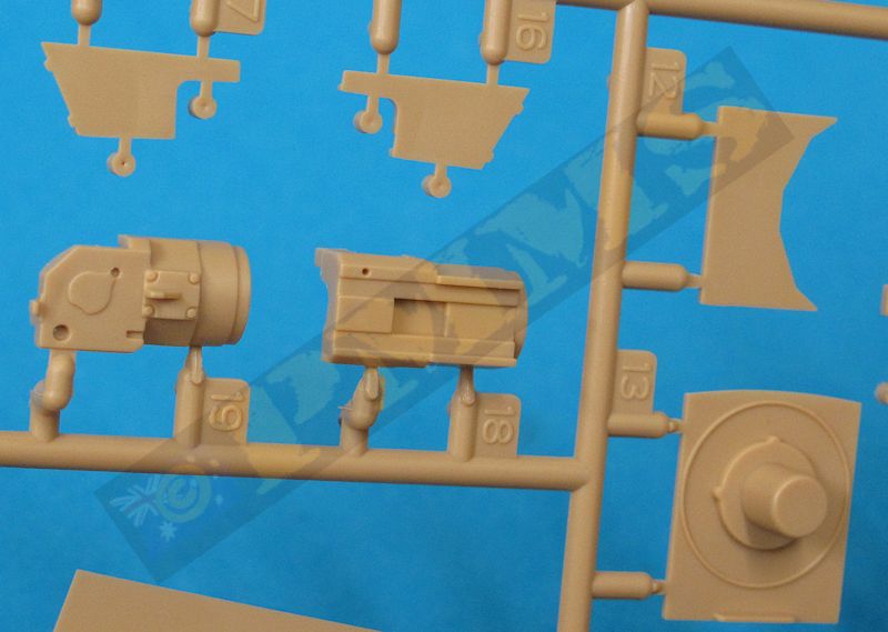
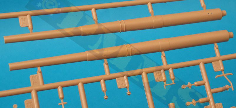
The main barrel gives you a choice of split plastic barrel or in tunned aluminium with fine rifling included inside the muzzle. The plastic barrel requires the join seam to be eliminated and includes etched brass rifling that’s inserted into the muzzle. The metal barrel would be the obvious choice and this is trapped between a three part breech with separate three part breech block. There are other smaller details added to the breech assembly including the breech lever that should be positioned in accordance with the breech block when open or closed. There is a small bracket (part J47) added to the side of the barrel tube and you need to cut off the locating pins when fitting to the metal barrel and just glue with cyanoacrylate and you can use the plastic barrel as guide to the right position for the bracket.
The gun cradle is in two halves with the elevation arc trapped between them and includes nice details on the outside and inside rib details at the rear but there are a few shallow pin marks and quite large plastic nodes to be removed from the inside which can be quite awkward and care will be needed not to damage the rib details.
As is common with many artillery piece kits the lower gun support slide doesn’t have the lip to allow this to fit to the cradle allowing the barrel assembly to recoil, you can add this if you wish for the correct appearance even if not planning on having the barrel in recoil with thin card strips glued to the undersides of the slide and trimmed when the glue is dry. The slide can then be glued to the bottom of the barrel/breech assembly as it should be and not to the gun cradle as indicated in the instructions. The forward section of the slide has separate bolt strips either side for a good appearance along with a separate front brake cylinder.
The recuperator cylinder support is in two halves with again separate bolt strips for the support base for good definition while the main recuperator is a central metal tube ensuring it is perfectly round with plastic front and rear sections plus the front support arms and this assembly fits snugly to the top of the recuperator supports and the arms to the gun cradle.
The barrel assembly can be slid into the lower cradle without glue to enable this is recoil back and forth after assembly as well as depicting the correct detail with the added lower slide strips.
At the rear of the cradle is a delicate folding ammo loading tray which you have the choice of fitting raised or lowered, care is needed assembling the cradle due to the small parts but nothing too difficult. The square gun base is easily assembled with the larger parts fitting perfectly although care is needed with some of the smaller parts to get the best fit.
The two large top carriage sides having nice bolt head details on the outsides but there are some shallow pin ejector marks to be removed from the inside faces while all of the carriage accessories are separate parts for excellent detail definition and there are separate shield supports for fitting the large shield.
This gun retains the large fuse setter box with etched top dial face on the left side but not the two shell holders as the fuse setter wasn’t actually used on the gun being purely for ground targets. Fine chain is provided for added detail but this is a little over scale in appearance.
The right carriage side has multiple details including, note the gun usually has both the traverse and elevation hand wheels and the azimuth and elevation data indicator dials but the the kit only has the single hand wheel and just the elevation data indicator dial and some images of destroyed vehicles show there are two hand wheels although not in the usual position.
The elevation data indicator has a fine etched dial face for excellent detail along with the rear quadrant scale which has fine gradients included on the part and a separate indicator arm and linkage to the main gun sight. This sight is made up of 13 very small plastic and 1 etched part for a very intricate assembly that needs care to ensure all the small parts are aligned correctly as you fit them, the instructions are not that clear with some of these so take care.
The larger multi-part mountings for the hand wheels go together well and the kit also includes a three part etched chain assembly fitted between the hand wheel mountings. The etched chain is in two halves giving link texture on both sides and care is needed when sandwiching the two chain sections together, the two part central mounting frame has to be carefully bent to shape and two very small plastic pullies are trapped between the frame and chains during final assembly with the chain ends fitted to the hand wheel mountings and the frame to the lower carriage. This all sounds quite complicated and it is in a way but if care and patience is used a very delicate and detailed sub-assembly results adding excellent detail to the overall appearance.
The two large recoil cylinders that extend out the front of the lower carriage are made up of four part plastic parts and outer metal tubes. When gluing the cylinder halves together the central piston should only be glued between the front cylinders halves (parts H43, H46) leaving the rear cylinder (parts H2, H3) free to move along the piston. The brass tubes fit over the front cylinders and glue to the rear cylinders only but I needed to reduce the diameter of the plastic cylinders a little to allow the tubes to fit allowing the plastic cylinders to slide inside the brass tubes.
The gunner’s seat can be fixed folded up or down depending if you choose firing or transport mode and the whole assembly is attached to the lower cradle support box assembled earlier.
The large gun shield is supplied in two plastic parts or in etched brass with workable hinges for the side plates, this allows you to show the shield in firing or folded travel mode. The etched shields are by their nature thinner than the plastic shields but these are not overly thick in any case and far easier to assemble with just the bottom shield to be glued in place. You can only use the plastic shields in the firing mode unless the side panels are cut off and repositioned for the travel mode. The hinges on the etched shields are a little tricky to bend to shape with the wire provided used for the hinge pins and the instructions give a plan view for the bottom shield angle so this can be bent to the correct angle without any problems.
The plastic shields have nice surface detail but both the plastic and etched shields are missing the sliding armoured cover over the top of the recuperator cylinder and this would have to be added from plastic card, this additional cover is clearly evident on any of the period photos of the vehicle.
Added to the rear face of the left shield is the large six round ready ammo box and this has perforated etched brackets added inside for loading the 88mm rounds provided, the separate outer box side has bevelled edges that results in a perfect seamless fit. The lid can be left open if you wish and the plastic shells have round etched base caps with engraved data.
The fully assembled gun fits easily to the pedestal mount on the rear hull deck but not it is not permanently fixed in place should you turn the model upside down for any reason, it does also allow you to paint the gun separate and fit easily to the hull.
The kit gives you the full engine even though it can’t be seen and builds quite easily without any major traps along with overall good fit of the parts and will build into an impressive kit of this huge brute that should be welcomed by modellers.
Rating 9/10
Build Detail Images

Click on thumbnails for larger view
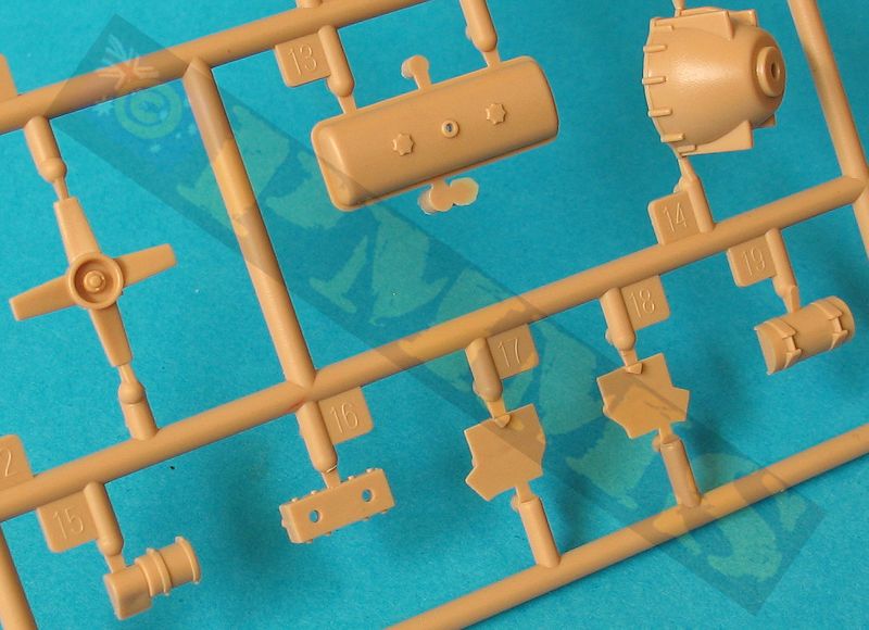
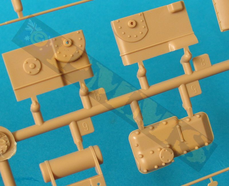
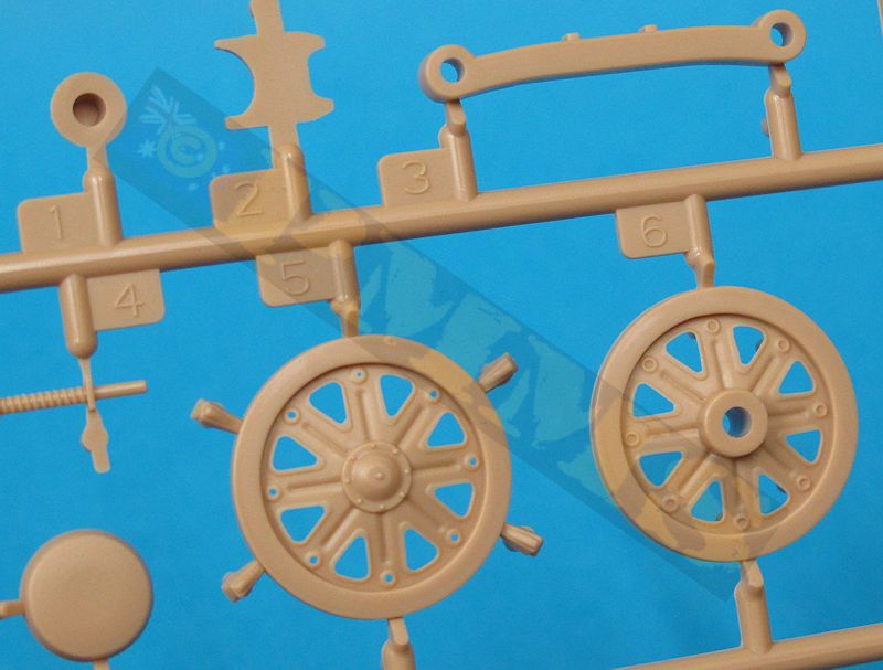
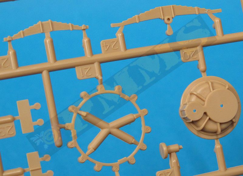
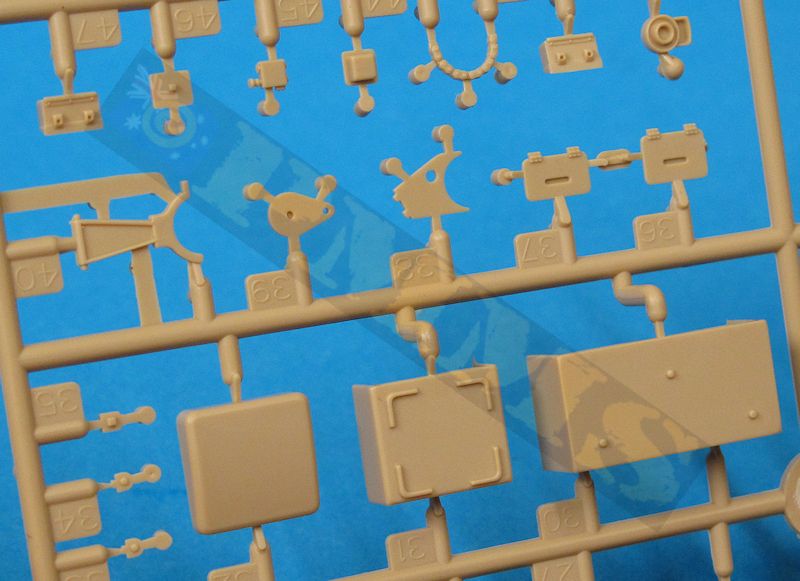
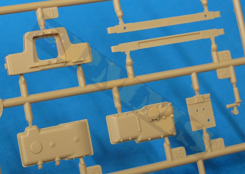
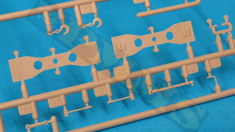
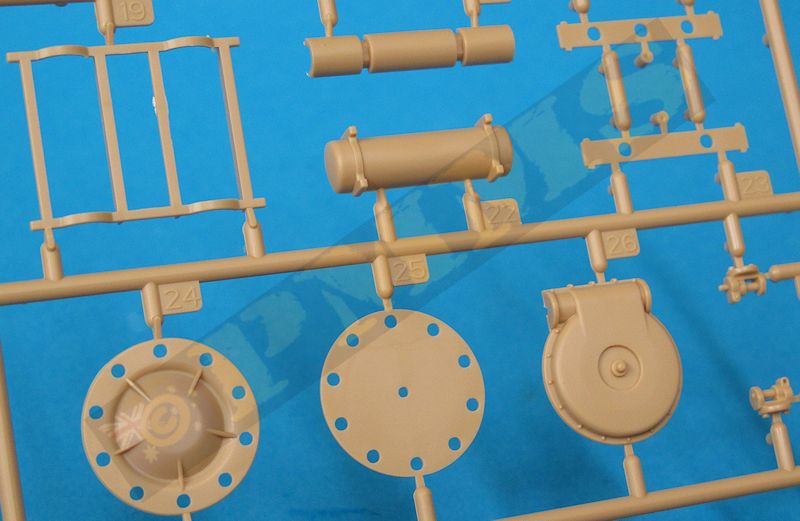
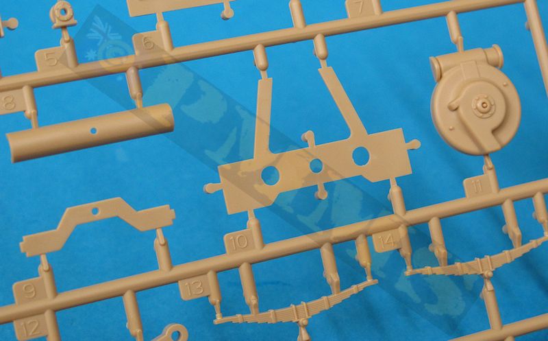
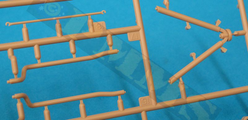
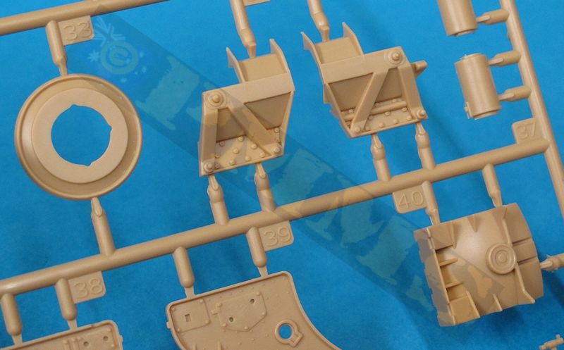
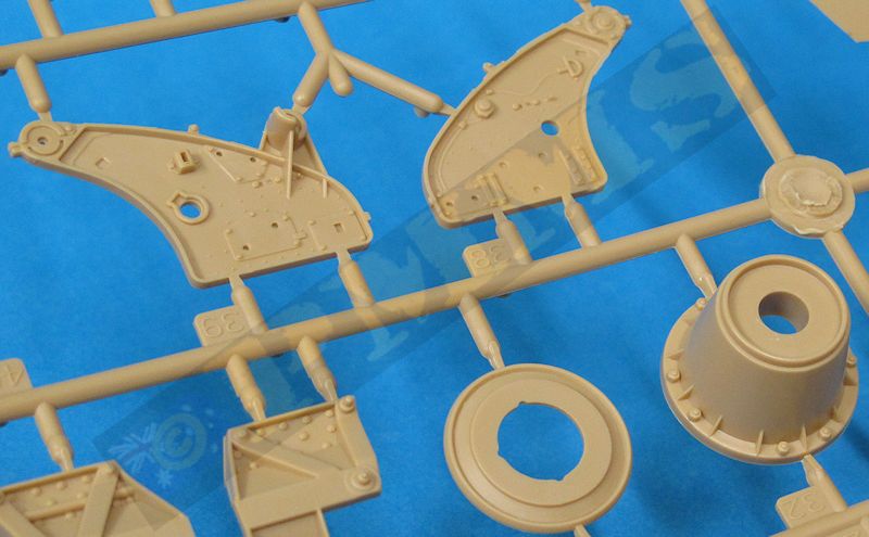
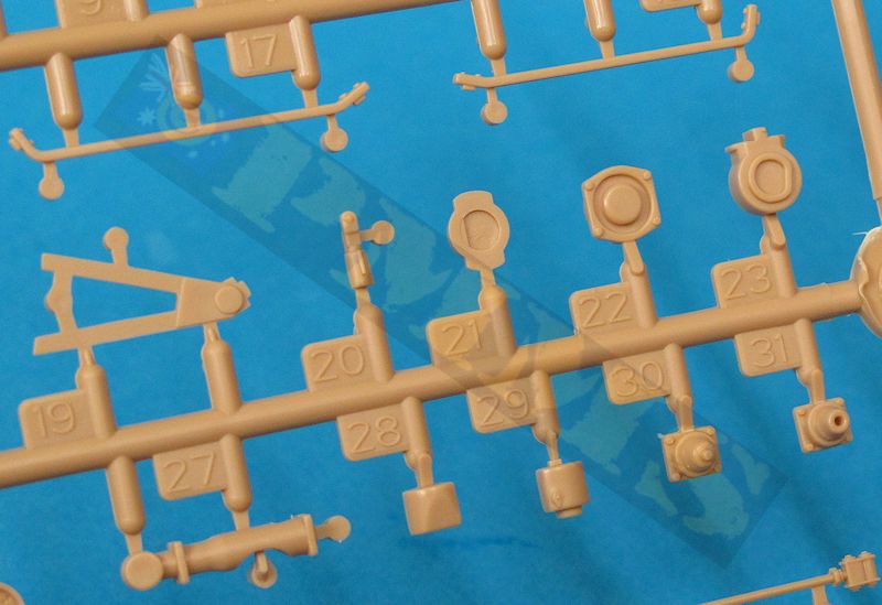
The Sprues
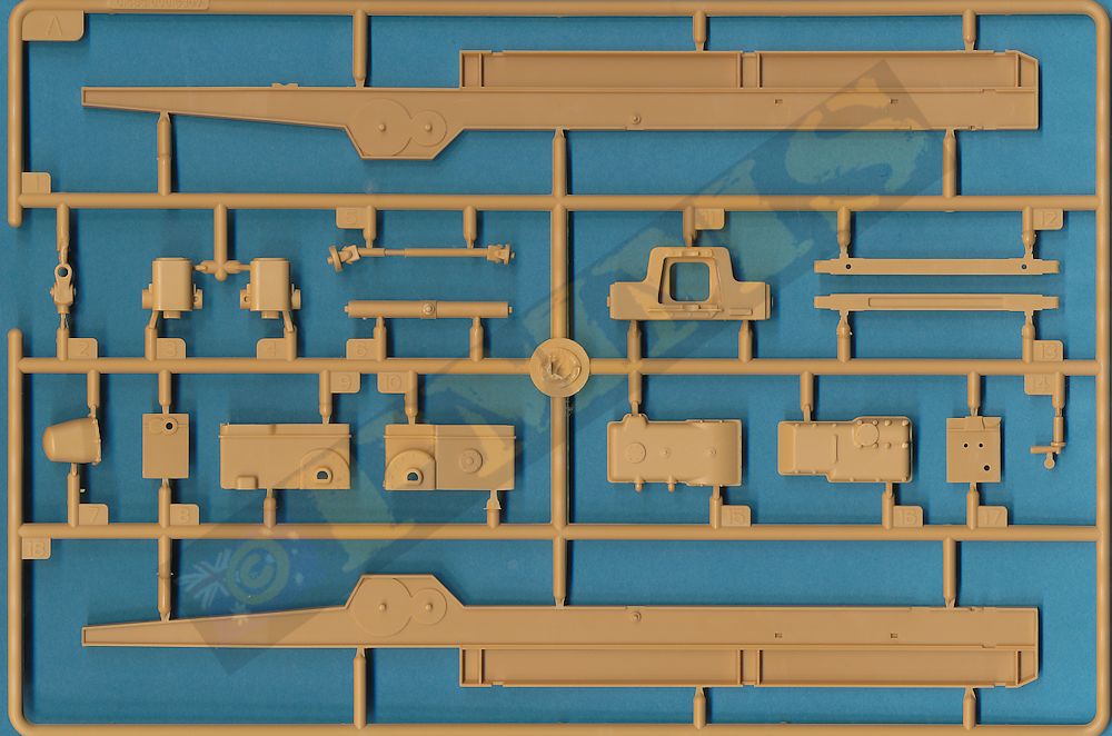
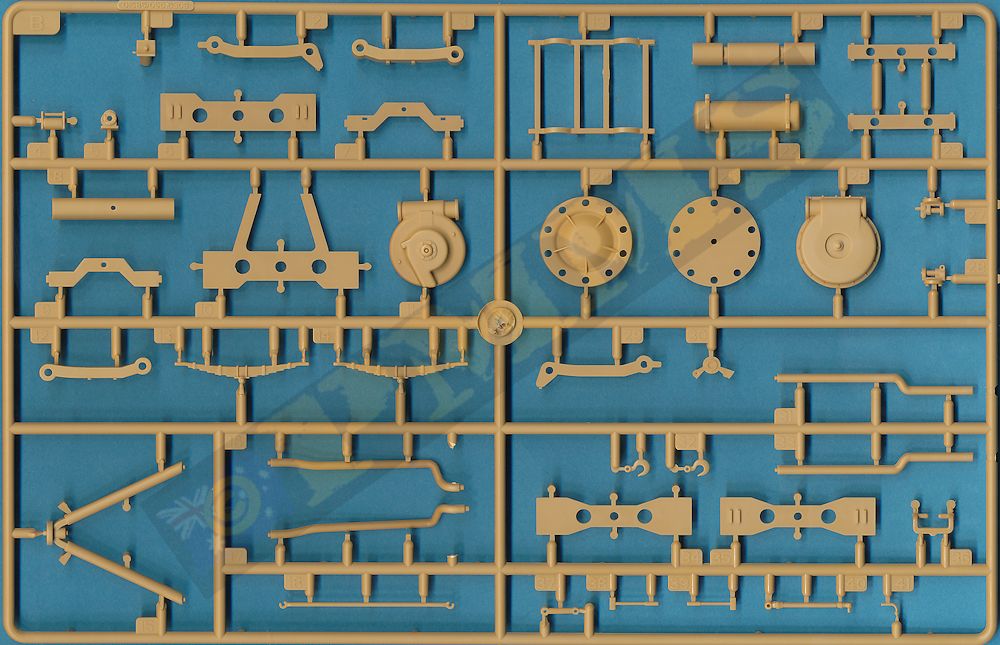


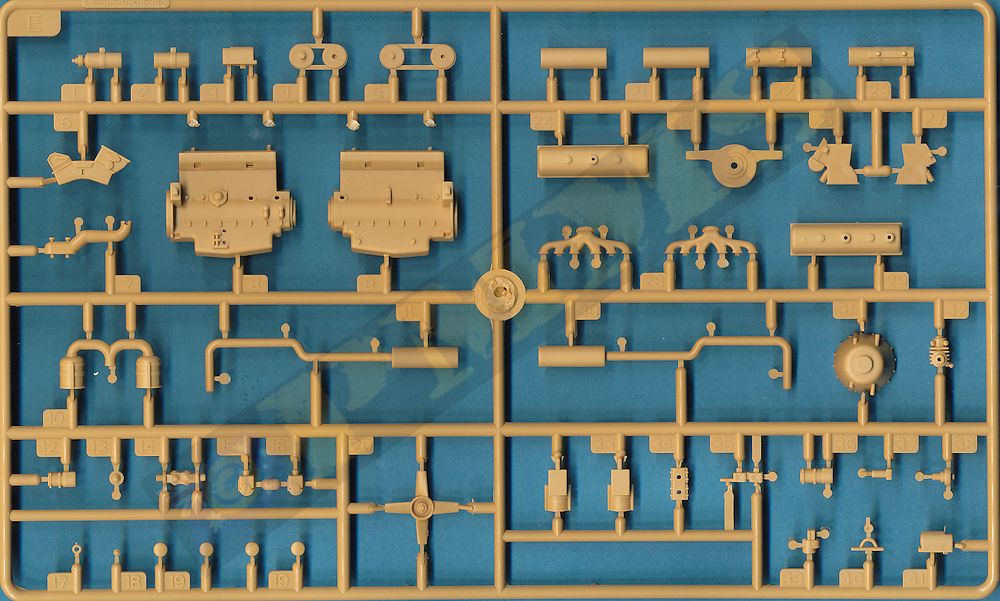
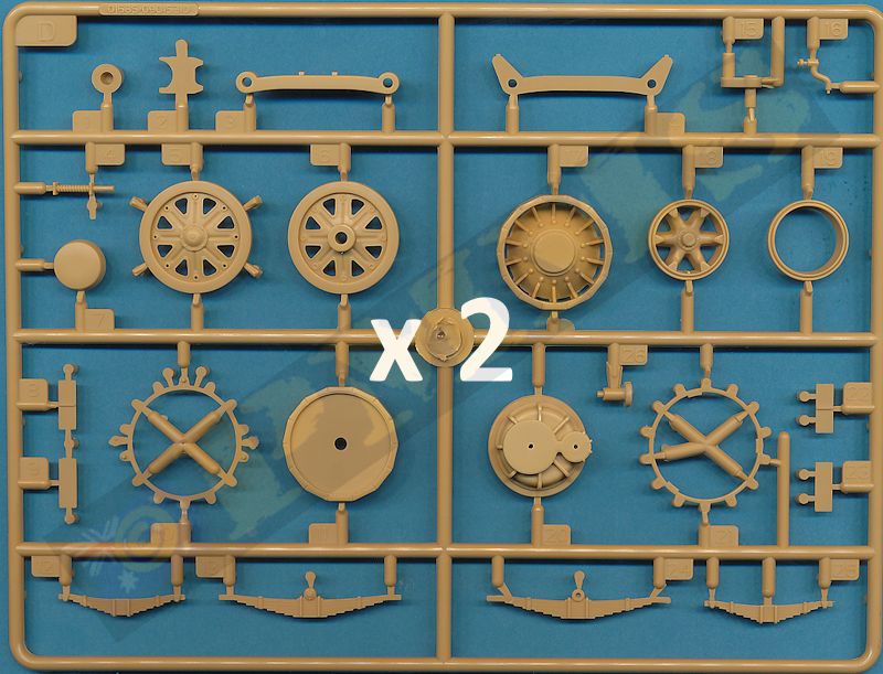
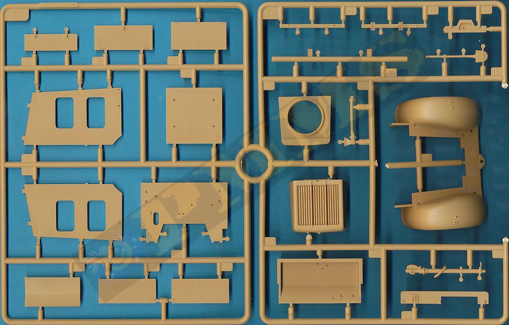
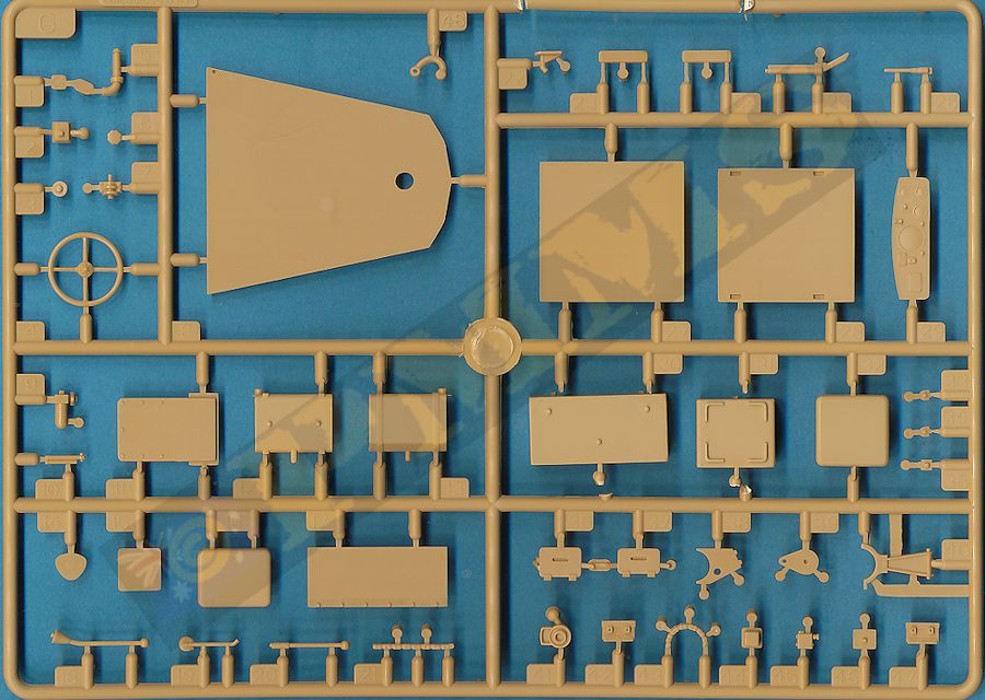
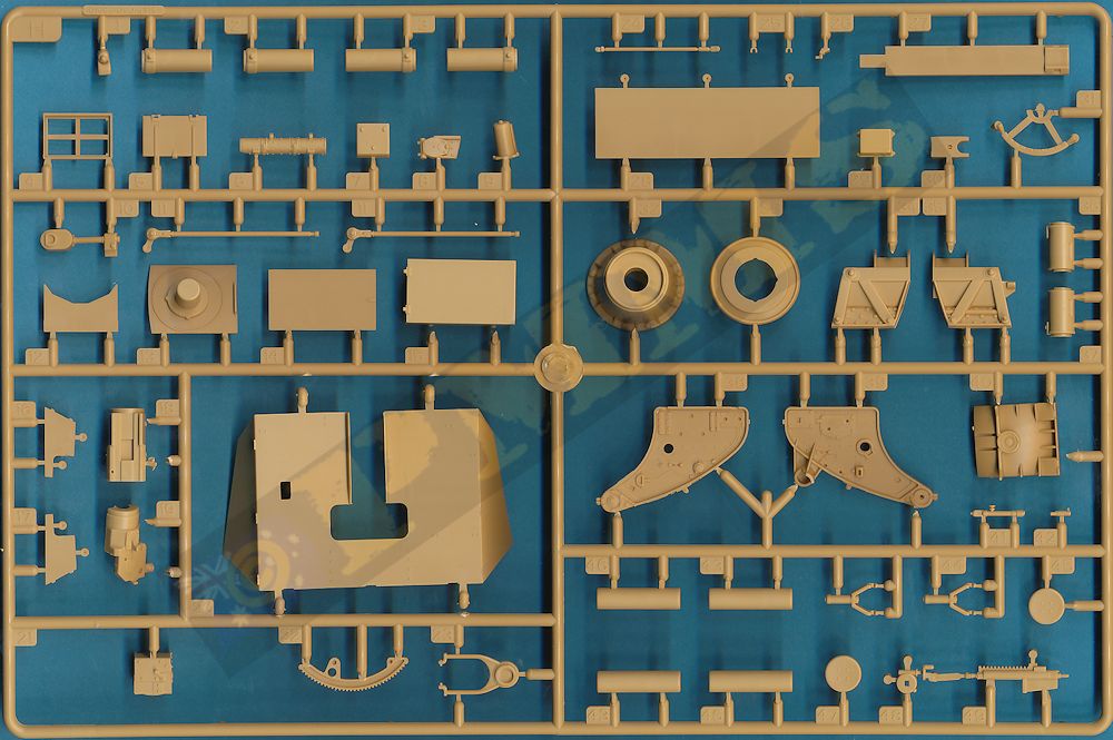
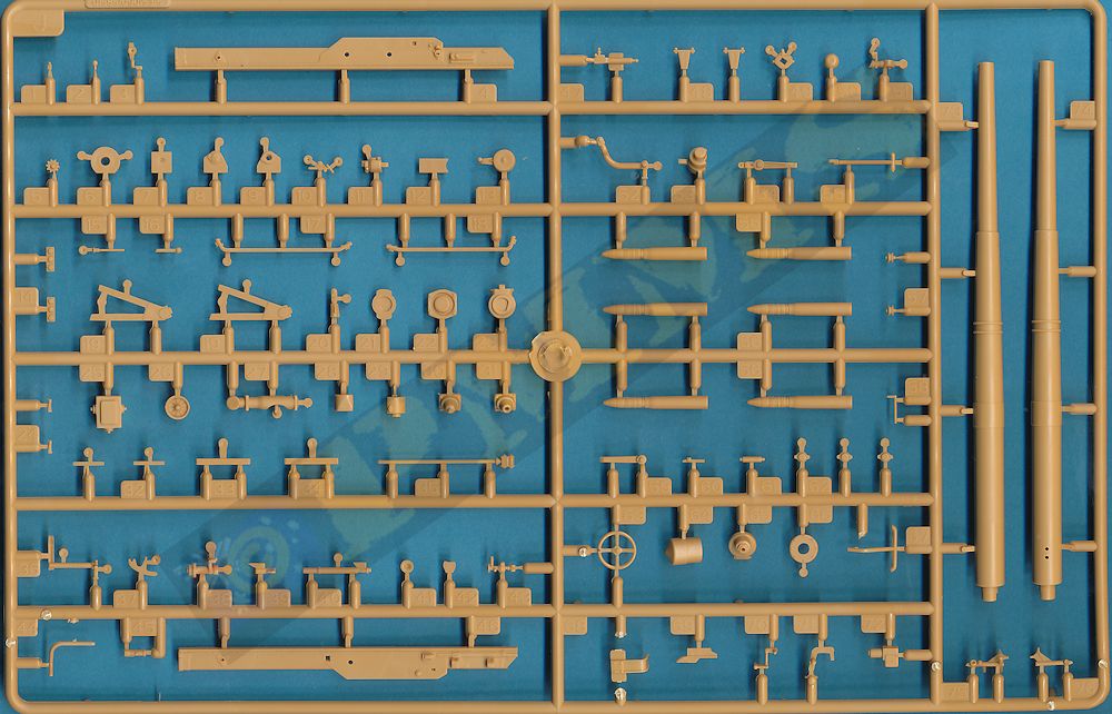
Sprue detail images


Close new window to return to page
| Schwerer Zugkraftwagen 12t and Variants (Daimler-Benz)(Sd.Kfz.8) Nuts & Bolts Vol. 16 ` 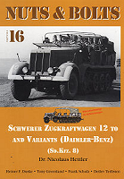 |
Panzer Tracts No.7-1 Panzerjaeger ISBN 0-9744862-3-X  |
| German Heavy Half-tracked Prime Movers 1934-1945 Schiffer Military History  |
Halftrack Vehicles of the German Army 1395-1945 Schiffer Military History  |
