

| Introduction: |
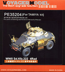
WWII Sd.Kfz.222 4Rad
Update Set
Voyager Model 1:35 set #PE35204
Review by Terry Ashley

| The Update Set: |
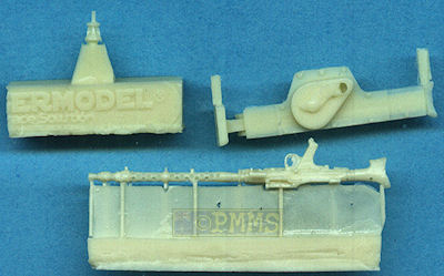
The resin parts are in light cream resin cleanly cast with just the small casting blocks to be removed which is very easy to do leave very little cleanup required.
I have used many of the available tools extensively over the last few years and have found the ones I resort to most often are the original Etch Mate (#EM-001), the newer Armour Extra Details EASYbend and for the really small jobs the 2” Hold and Fold “Bug”.
Many of the etched parts provided replace kit parts completely and there is actually very little surgery needed on the kit, with the major jobs being cutting all the clips from the tools, removing the equipment box and jerry can brackets and the fender locating lugs as well as cutting out the rear engine compartment panel and some of the smaller parts for the 20mm gun and it’s best to trim all these before you start adding the etched parts.
| The Hull: |
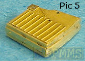
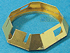
Along the left hull side are the large storage boxes which are completely replaced with brass and the larger box will require some careful bending as some sections require you to bend the segments in opposite directions so work out what is the best sequence for these before starting and the top and lower front doors can be made workable with full width hinges that again require careful bending with the wire provided used for the hinge pins. It is best to solder these boxes together for greater strength and soldering from the inside will reduce the amount of cleanup required.
All the door latches and wing nuts are supplied as small etched parts that can be added and the two lower lockers also have the doors hinged with additional latches for excellent detail definition. Even if you do not make the hinges workable still bending the hinges around the wire pins and fitting the doors closed will result in excellent detail definition.
These boxes are not for the fainthearted and some previous experience working with etched brass and soldering will certainly come in handy as will a good dose of patience.
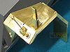
On the hull all four fenders are replaced with etched parts and again there is some careful bending required with the storage compartments on the front fenders again having separate lids but not workable hinges in this case.
You have to be careful bending the outer lips of the fenders as these are rounded curves and the fenders have a wide textured bend lines on the underside to help get the more rounded curve but care is needed.
I have assembled the front left fender to see how it all goes and annealing the outer section for the curve by running through a candle flame until red hot and then let air cool (which only takes a minute or so) will make getting the nice curve much easier.
I made a jig for bending the curve by rounding the edge of the thick piece of plastic card which again aided in getting a good even bend, this bend should be added before any other bending takes place.
The contours of the fender are added next which is very easy due to the perforated bend lines on the inside and a small dab of solder added on the inside of the join to hold the fenders in place. The inner frame for the storage box is bent to shape which again is easy due to the perforated bend lines included but watch the direction of the bends as the instructions could be clearer on this.
The lower angled section (part A18) is added next and this will really test your patience as there is no locating ridges or any other to help out and holding this in the correct position for soldering flush with the front lip of the fender will need care. Using a multi-clip tool or similar would help but in the end due to the precise location of the front join I used my fingers (with folded tissue insulator) to hold the parts firmly in place before adding a couple of quick solder spots to achieve a bond, you have to have the soldering iron tip very hot and be quick as the tissue will only work for a few seconds before the fingers know about the heat. Finally the join is securely soldered using tweezers to hold the parts but there was an issue in that part A18 also forms the inner wall of the fender storage box but it did not extend to the outside of the box opening leaving a gap of just over 1mm.
This will not be a problem if the box lid is kept closed and I filled the gap on the underside of the fender with a 1mm strip of left over fret which is visible in the images of the fender assembly but again won't be at all noticeable with the box lid closed.
The separate box lid requires very thin edges be bent and using a good bending tool will do the job quite easily and as mentioned the lid hinge is not designed to be workable so you must decide if you are going to show the lid open of closed during assembly.
One issue with the storage box compartment is the perforated top bend leaves behind small holes that give the impression of a hinge along the outer edge and you may want to fill these small holes with solder and file smooth early in the process as they can be seen after final assembly (see images).
Added to the front fenders are the brass width indicators, and multi-part turn indicators as well as the pennant support plus the underside support brackets that give added strength to the hull join just like the real brackets and there were no real problems bending and added these parts to the fenders.
The brass width indicators are actually the wrong style for the 222 in that the lower thicker section should extend further up the indicator shaft than they do, the instruction diagrams show this correctly so maybe the wrong style indicator post with short base was included in error?
The fit of the assembled fender to the kit hull was spot on and given the number of bends and angles in the fender and the hull at this point this is a very good result. This one fender took a couple of hours to assemble and solder together so doing all four could be a solid days work but the end result looks impressive.
The rear fenders again have curved outer lip and the underside supports and mud flaps as well as the taillight mounting bracket and light face and these assemble in basically the same manner as the front fenders with soldering the best option. I should also mention that soldering the joins from below the fender will leave a lot less cleanup on the outside to contend with making for a cleaner finish.
Other hull details include all the visor rain guards in multiple parts that will require careful fitting plus all the tool brackets as mentioned that include the front smoke grenade brackets, the jerry can racks other smaller brackets. The jack mounted on the right rear fender is provided as an etched part with excellent detail with additional etched mounting brackets for good definition and you can actually make the jack bracket clips workable if you wish?
At the back is the engine intake louvred panel has very fine louvers with a separate solid rear hull plate that is bent to shape and fitted over the and louvred panel as often seen on operational 222s.
The fine screen on the top of the hull behind the turret is in one large piece with extremely finely etched screen mesh, but this unfortunately is the wrong mesh design for the 222 being a generic square mesh while the actual screen has a distinctive diamond shape to it. You can either add the mesh panel over the moulded kit mesh or cut this out completely leaving just the etched screen which will require you to blank off the insides of the hull to avoid the see through look.
| The Turret: |
Due to the various angles of the turret and the base ring it was virtually impossible to get any of the clips, tweezers or other aids to get a grip and again I resorted to holding the turret shell and ring together by hand and spot soldering quickly to get the initial join and then completing the join is sections.
For the front of the turret is an additional armour panel and this gives the small lip around the front turret openings for a good appearance.
But before bending the turret to shape you need to bend the top hinge attachments using the wire provided as it is nearly impossible to bent these later, and care is needed no to damage these during the rest of the assembly but there are quite robust once bent to shape.
There are small angles fillets added inside the front of the turret and these can be added using thin cyanoacrylate will do the job nicely as they are too small for soldering in such confined spaces.
Added to the turret are the side kit visors while for the rear visor you can either use the kit visor or the etched substitute with fine workable hinges and added to the rear sill is a small etched bracket and resin aerial base.
The top screens have the frames separate and these require extremely careful bending as the frames themselves are quite narrow and it is easy to distort these while bending if not held tightly in the bending tool. Once bent to shape the separate fine mesh is added and this does make the assemblies more robust but they are quite fragile and you should handle these with care during assembly.
Attaching the separate small hinges will need care as you have to line these up with turret lip hinge attachments and careful planning will be needed here if you want workable hinges, but if not you can just glue the screens in the raised or lowered position.
The lower turret ring added earlier fits perfectly into the Tamiya turret ring with very little if any movement but be careful as the turret is not attached and will come adrift if you turn the model upside down later.
| 2cm KwK38 gun: |
Both the KwK38 barrel from armorscale (#B35048) and Griffon Models (#LB35006) are the correct length and I have used the Griffon Models barrel to update the set further.
The turret itself matches available data very well and takes into account the sides are not flush with the hull sides as depicted in the Tamiya kit but in fact are about 1mm inboard as shown in photographs of the 222 turret/hull and the 1:35 plans in the Panzer Tracts No.13 Panzerspaehwagen “Armored Cars Sd.Kfz.3 to Sd.Kfz.263” book.
The kit gun gets a new small front shield that requires you to cut away the moulded on shield (about the only surgery needed) as well as replacement spent shell chutes for the 2cm and MG34 plus the 2cm magazine bracket and fine sight ring.
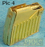
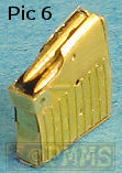
Also included are the small 10 round etched magazines from the Voyager set #AP066 which assemble into superb magazines but there are only 2 x 2cm rounds included in this set if you want to show the magazine out of the receiver. (see the full review of set #AP066 for assembling the magazines).
Note; there are just two brass 20mm rounds included with this set
As the resin gun includes the handgrip and trigger which the kit gun doesn't I opened up the mounting plate for the MG34 to allow this to fit in place like the real thing but you could just cut off the resin handgrip if you wished?
While the resin barrel cooling jacket looks very good I chose to replace this with the metal Adlers Nest MG34 barrel (set #ANM35-006) to enhance the appearance even further but this is up to the individual and the resin barrel will look okay after careful painting.
| Conclusion: |
This is most noticeable when assembling the major components such as the large hull storage boxes, the four fenders and the turret which is actually most of the set making this not one for the inexperienced.
But the added details makes the efforts worth it with the Tamiya kit getting a major makeover with the correct width of the turret noteworthy.
Highly recommended 7.5/10
| Etched and other parts |
Etched Parts
Click for larger views
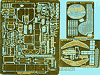
Close new window to return to review
| References: |
 |
Toadman's Sd.Kfz.222 Photo Detail CD Detailed photo walk around on the Sd.Kfz.222 |
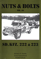 |
Sd.Kfz.222 & 223 Soft cover Currently out of print but excellent reference if you can find a copy. |
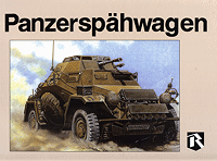 |
Panzerspähwagen Hard Cover |
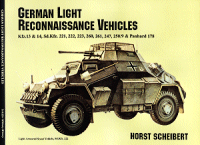 |
German Light Reconnaissance Vehicles Soft cover |
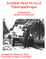 |
Panzer Tracts No.13 |