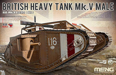
British Heavy Tank Mk.V Male
Meng Model 1:35 Scale Kit #TS-020
Review by Terry Ashley
Part 2 the Kit Build
Page 2 of 4
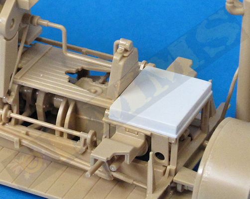
There is one item missing from the kit interior and that is the Commander’s stand for when he stands in the top Commander’s cab, this stand should be located on top of the square frame resulting after parts F15, F17 and F38 are attached and you will need to make this stand from plastic card if showing off the interior. It is fairly easy to make being basically a square box stand that sits on this frame. Note I have made this stand based on the drawings in the Osprey book on the Mk.V but I have seen images with a different arrangement for the stand, as we know some details differed between vehicles this could also be the case here, or then again the illustration may be wrong?
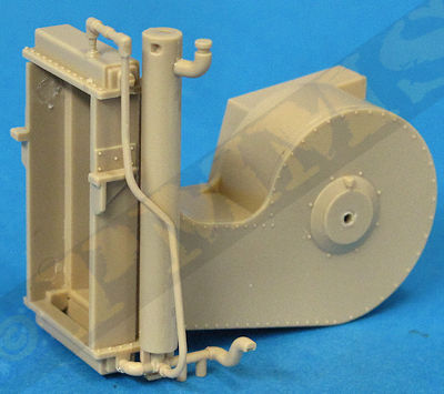
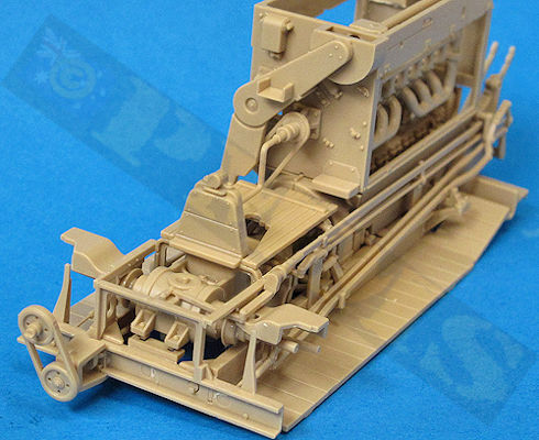
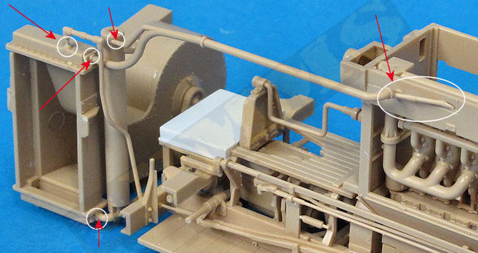
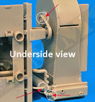
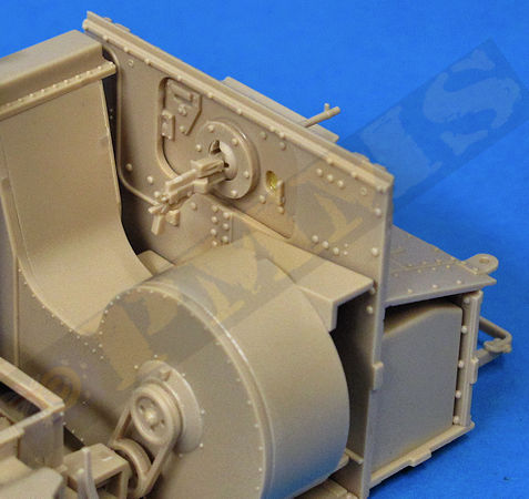
To attach the water tank/radiator to the rear of the engine/transmission assembly I glued the bottom pipe from the water tank to the radiator and then glued pipe G22 from step 24 to the water tank to the top of the radiator, also the rear mounted pulley F25 (from step 17) is glued to the radiator to secure the other side of the radiator assembly. And finally the top pipe G9 is glued to the water tank/radiator and to the side of the engine compartment (from step 24), this is then left to dry completely and will hold the radiator assembly in place quite securely to allow this to be displayed separate from the kit. (see images)
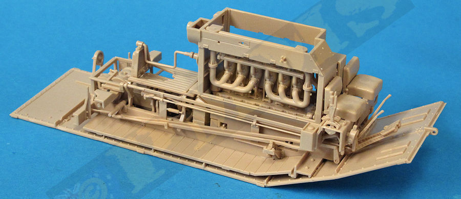
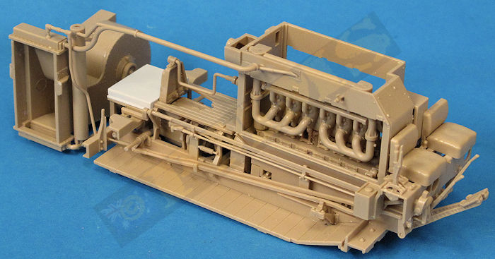
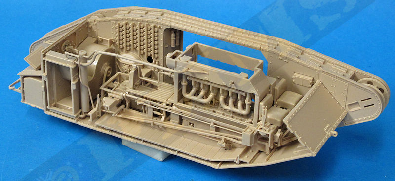
The radiator and engine assembly on the hull floor as per instructions.
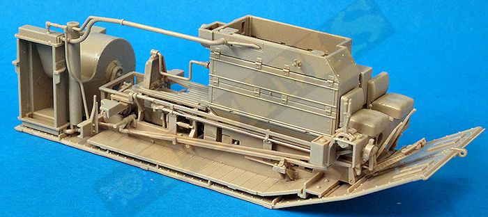
The radiator and engine assembly separate from the hull floor.
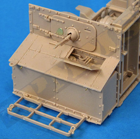
The rear hull plate also has the rear opening hatch as a separate part, this hatch can be shown open or closed with small pins on the hinge to fit in either position with you simply cutting off the redundant pin not required to allow for a positive fit of the hatch. There is also the Hotchkiss air-cooled .303 MG in the Skeens ball mounting added to the hatch and this the same mounting as on the front driver’s plate and the two sponsons so the assembly will be the same for all four installations.
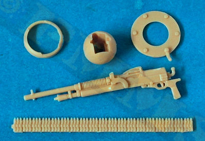
The Hotchkiss has nicely done details on the receiver and barrel as well as an additional ammo belt that can be bent to shape as required although as you can’t see the receiver once assembled unless the hatch is shown open the belt can be dispensed with. It is best to first glue the inner ring mounting (K3) in place and let the glue dry completely before fitting the gun so this gives a firm footing for fitting the gun.
The MG is first glued into the Skeens ball mounting which also has the sight aperture included in the ball, also make sure to remove the mould line from the ball mounting so this will move within the mounting ring, the MG and ball are then slipped through the opening and secured in place with the front attachment ring (K5), make sure you use glue very sparingly when attaching the ring to allow the ball to swivel as there is not a lot of clearance and any excess glue will get to the ball mount. After assembly the MG/ball will move freely in any direction but as there is nothing to keep it upright in the mounting so just make sure it doesn’t sit on an angle, easily repositioned if it does.
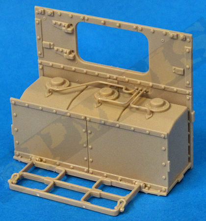
Finally step 24 shows the entire rear plate/fuel tank sub-assembly is attached to the back of the radiator assembly but if you are leaving the interior separate as described above then glue the sub-assembly directly to the lower hull plate (B5) ensuring this is at right angles and left to dry for later.
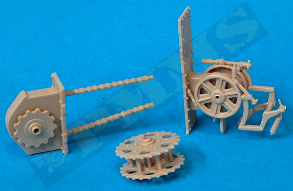
The two idler wheels are also fitted together without problems and I also assembled the two drive sprockets at this stage ready for fitting in step 28 and 32, this allows the glue to dry fully before fitting in place.
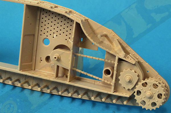
In any case the rear mounted transmission gear consists of the rear chain drives and smaller drive wheels designed to intermesh with the driver sprockets to drive the tracks plus the forward transmission gear. If using the inner drive wheels (H4, H5) make sure these can rotate after assembly but there was a problem meshing the drive wheels with the main drive sprockets that we’ll look at more closely in step 28.
The inner sponson bulkhead walls have nicely moulded on .303 ammo box faces and other details that went together without problems but as mentioned this can’t be seen after assembly, so it’s up to you if you fit these parts or not?
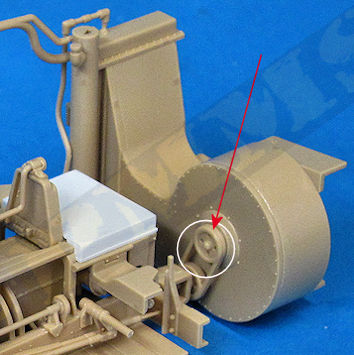
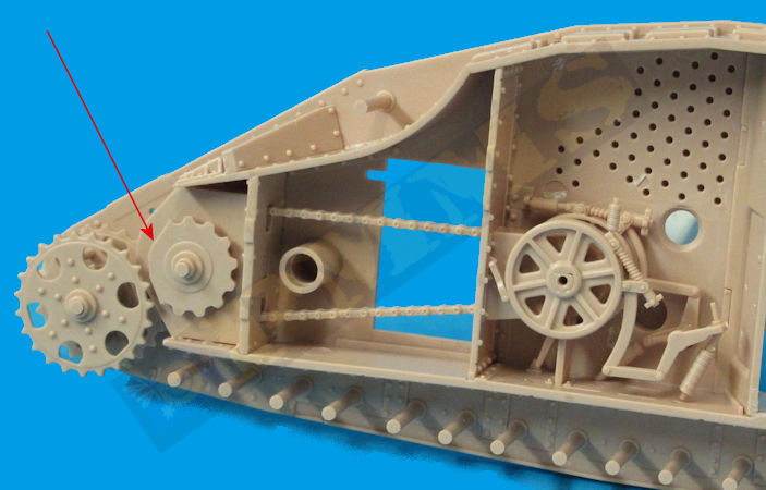
There was a issue here in that I could not for love nor money get the inner drive wheels to intermesh with the drive sprockets, this was the same for both the left and right sprocket assemblies and after numerous tries I simply cut away a few teeth from the smaller drive wheel to clear the drive sprocket and glued the wheel in place leaving the drive sprockets free to rotate. As mentioned you can’t see these inner wheels so leaving them off completely wouldn’t cause a problem, they can only be seen if you are building the model with the track off the rear sections of the frame.
The top full length bulkhead is also attached in the step and there were no problems here but again make sure this is glued snugly to the track frame section.
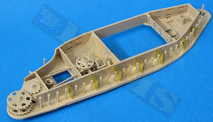
The instruction illustrations are very clear on the location of the large and smaller road wheels and the smaller wheels intermesh between the flanges on the larger wheels so you need to fit these together as you slip them over the axle stubs which aren’t a problem once you get the hang of it. There is also the small rear brace (H22) and forward panel (N13) added and you are ready to attach the outer armour section.
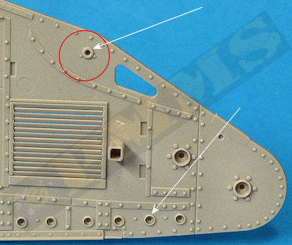
The fit of the outer armour was good apart from one issue, the locating hole for the top mounted road wheel axle was way too small and needs to be drill out to 2.6mm diameter (the same as the for the lower road wheels axles) just make sure you don’t drill all the way through the panel while enlarging the hole.
When gluing the armour panels it is best to work from one end and glue a small section holding tightly together till the glue ‘goes off’ and then move along and glue the next section until the entire hull sections are glued together. I did find that I needed to firmly clamp the hulls together at the corners of the lower sponson opening to get the tightest fit here and leaving clamped till the glue had dried completely, the result is a perfect fit of the track frames assembly.
There are additional smaller details added to the inside compartment but again these can’t be seen unless you are displaying the interior in some way otherwise you can just bypass adding these additional parts.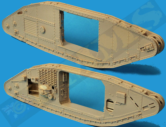
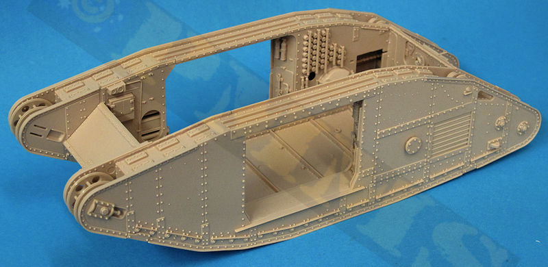
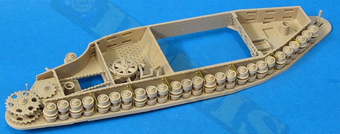
The fit of the hull sections was good but you again need to work from one end and hold the sections tightly to together as you go for the most snug fit as there is a lot going on and you need to make sure everything is a snug as can be for the best result.
Fully assembled main hull without the interior fitted.