
Faun SLT-56
Tank Transporter
Kit Construction
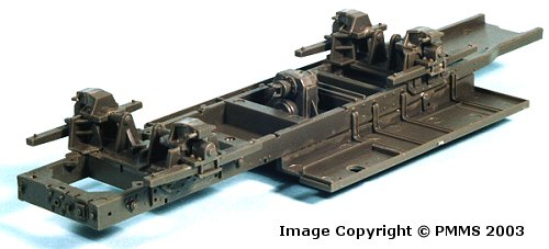
Step 6 to 10 Chassis and Suspension
by Terry Ashley
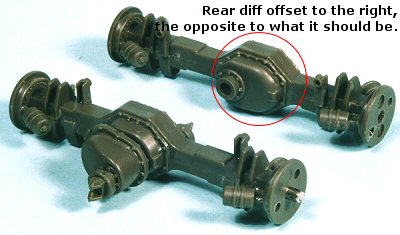
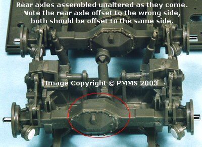
Step 7 and 9: Rear axle assemblies:
The assembly of the rear most axle in Step 7 had me scratching my head initially
as the instruction diagrams show the parts with the correct orientation
but the actual parts are a mirror of what they should be in relation to
the position of the differential housing. The actual diff housing is offset
to the left (when looking from the rear and as shown in the instructions)
but the kit part housing is offset to the right, this means the forward
diff cover (part D17) has to be glued the opposite way around than shown
in the instructions, the locating notch on part D17 will make you fit it
this way.
The inner rear axle (Step 9) has the parts and instructions with the correct
orientation so you end up with the two diff housings offset on opposite
sides when assembled, at the end of the day this will probably not be
that noticeable on the finished kit as it will be on the undersides and
does not affect the look of the finished kik but did exercise the grey matter
to work out what was happening.
If you want to fix this you will have to relocate the shock absorber mounts
(parts C59) on the opposite side of the lower axle (part D22) and fill the
original locating holes, and then glue the two diff housing covers (parts
D17 and D18) on the opposite sides of the diff housing. The rear diff cover
also has the FAUN logo embossed on it so this will also need to be reversed
so the lettering is the right way up after swapping sides.
Apart from this the assembly of the two axles was straight forward with
no problems other than the usual cleanup of the join seams between the two
axle
halves. The metal shafts added through the axles fitted precisely but I
did need to open up the hole in the centre of the brake drums (parts C54)
on each
wheel to fit over the shaft better, also watch the direction of the brake
cylinders (parts C60, C61) added to each drum as they are reversed on each
side so that part C60 faces the front on each. Parts C61 had small sink
marks in the ends and I used thin discs of plastic card (made with a punch
and die)
to cover these, although you could fill and sand if preferred?
The instructions show there should be five drive shaft universal joints (parts C62) but only four parts 62 are supplied in the kit. Although I did find part D3 lurking unannounced, which is another U/J but slightly larger than parts C62, this fifth U/J can be used on the rear of the main central transfer case leaving the other parts C62 for the diffs.
Step 8 and 10: Front axle assemblies:
Assembly is straight forward with again only the join seams between the two
axle halves requiring cleanup. The design of the parts allows the wheels
to be positioned at any angle but the wheels aren’t connected and
move independently so you could have some strange looking wheel angles although
the instructions indicating to glue them in place at the desired angle.
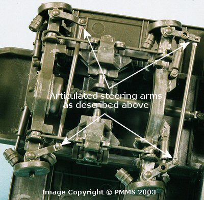
It is also possible with a little modification to make the wheels steerable so they can be positioned at any angle without gluing.
The modifications are to the steering arms (part B23 for the front axle and part B36 for the second axle) and entail separating the steering arm from the two end connectors, then re-attaching with a pin to allow movement.
| 1. Drill a small hole through the bolt head on the end of each arm, this will ensure the correct position when re-attaching. |  |
| 2. Using a sharp blade carefully separate the arm from the end connectors taking care not to damage the parts. |  |
| 3. Insert a small pin from stretched sprue into the end connector hole and allow the glue to dry. |  |
| 4. Insert the pin through the hole in the steering arm. |  |
| 5. Heat a small flat screwdriver head in a candle flame (taking the usual care with a naked flame) and melt the pin end down to secure the join. |  |
| 6. Repeat on the four steering arm ends for the two front axles. |  |
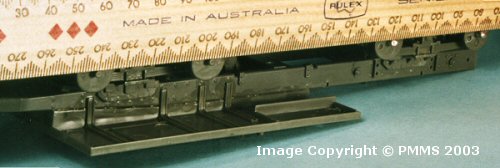
The eight axle assemblies can now be fitted in place on the main leaf springs (from step 6) but take care when fitting these as it is possible for the axles not to be aligned parallel due to the leaf springs pivoting action. To ensure the four axles are aligned correctly “sit” a ruler on top of the four axles and make adjustments till all four axles are parallel and then glue the leaf springs in place at their central locating point.
Also remember to fit the drive shafts (parts D2, D4 and E39) between the diffs and central transfer case as you fit the axles in place as it’s difficult to add these later. The drive shafts simply clip into the universal joints without the need for glue which makes assembly easier.
When the axles have been aligned correctly and the glue dry add the shock absorbers (parts C2, C3 front axles and C34, C35 rear axles) and the stabiliser bars (parts C58) on each wheel.
Tractor Assembly: Steps 1 to 24.
Step 1 to 5: Cab Assembly.
Step 6 to 10: Chassis and Suspension.
Step 11 to 13: Fuel Tank, Spare Tire and Chassis details.
Step 14 to 19: Rear Tractor Assembly (1).
Step 20 to 22: Rear Tractor Assembly (2).
Step 23 to 24: Adding hoses and piping.
Trailer Assembly: Steps 1 to 14.
Step 1 to 5: Deck underside and Suspension.
Step 6 to 7: Gooseneck Assembly.
Step 8 to 10: Final Deck Assembly.
Step 11 to 13: Ramp Assembly.
Step 14: Attaching Trailer to Tractor.
Return to the first look review of the kit.
Page Update 14 September 2003